|
| |
TM 5-4210-220-12
4-30. REAR AXLE - Continued
4-30.4 Brake Assembly - Continued
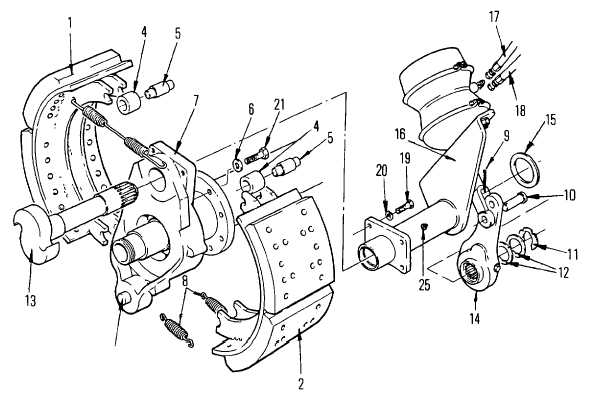
(4) If replaced, install new brake spider (7) using hardened washer (6) and bolts (21). Apply threadlock
liquid (item 29, Appendix E) to bolt thread. Install and tighten bolts to 115 ft lb (155 Nm).
(5) Install air chamber bracket (16) to spider (7) using bolts (19) and washer (20) Tighten bolts
to 85 ft lb (115 Nm)
(6) Apply a light coat of pipe sealant (Item 22, Appendix E) to thread of fittings and install brake
chamber hoses (17 and 18) to brake chamber. Tighten fittings firmly to provide leak proof connections.
(7) Apply a light coat of grease (Item 16, Appendix E) to journals and splines on camshaft (13), and
slide it through spider (7) and brake chamber bracket (16). Be careful not to damage seals inside
bracket tube. Be sure that no grease had been left on camshaft head.
(8) Connect brake shoes (1 and 2) together using retaining springs (8). Place brake shoes around axle
spindle so that lower end is riding on anchor pin (A).
(9)
Install return spring (3).
(10) Lever each brake shoe in turn and install cam rollers and pins (4 and 5) between brake shoes
and camshaft head.
4-574
|