|
| |
TM 5-4210-220-12
4-30 REAR AXLE - Continued
(21)
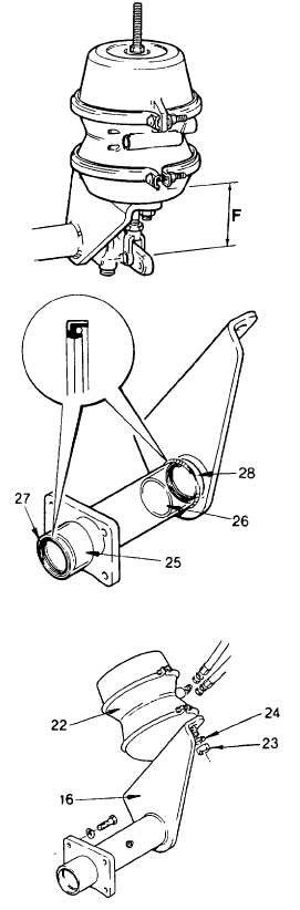
If brake air chamber is replaced, adjust
clevis position and push rod so that
distance F from chamber to center of clevis
pin holes equals 2 5/8 ± 1/16 in. (66.7 ± 1.6
mm).
CAUTION
Do not reuse a brake drum if the diameter
of the bore exceeds the manufacturers
recommended maximum or the total
indicated runout exceeds 0.020 in. (0.51
mm).
(22) Inspect brake drum for cracks, heat-checks,
glazing, grooving, runout and out-of-round.
If brake drum is cracked it must be
replaced. If drum is glazed, grooved, out-
of-round, etc, it may be turned in a lathe
and
reused
provided
the
maximum
diameter of the bore, stamped inside the
drum, is not exceeded.
INSTALLATION
(1)
If bushings (25 and 26) are replaced, use a
suitable
piloted
punch
to
drive
new
bushings in place. When correctly seated
bushing (25) should be in 1/4 in. (6.4 mm)
from end of tube and bushing (26) 21/32 in.
(16.7 mm) from other end of tube.
CAUTION
Improperly orientated seals may allow
grease to leak out of camshaft head and
contaminate brake drum and brake shoe
lining
(2)
Install seals (27 and 28) using a suitable
pilot. Be sure seal springs are facing in the
same direction, toward air chamber end of
bracket.
(3)
If
disassembled,
assemble
brake
air
chamber (22) and air chamber bracket (16)
using washers and nuts (23 and 24). Be
sure air hose ports in brake chamber face
away from bracket. Tighten nuts to 170 ft
lb (230 Nm).
4-573
|