|
| |
TM 5-4210-220-12
4-30. REAR AXLE - Continued
INSPECTION
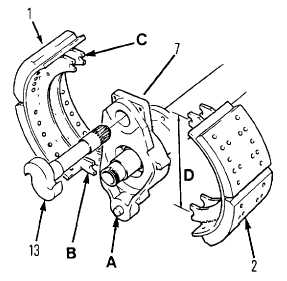
(1)
Inspect anchor pin (A) If pin is loose or
grooved more than 0.03 in. (0.8 mm) below
original surface, replace the spider.
(2)
Inspect brake shoes (1 and 2) and replace if
lining is contaminated, cracked or worn to
less than 1/4 in. (6.4 mm) thickness at any
point, or if rivets are closer to surface than
1/16 in. (1.6 mm) in any location.
(3)
Check brake shoes for bent or cracked
webs or table. Check also for broken weld
seams, loose rivets or elongated rivet
holes. Replace shoes if any of these
conditions are found.
(4)
Check shoe span by measuring the distance D
between centerlines of anchor pin and camshaft
roller recesses. If D is less than 12 5/16 in.
(312.7 mm) or more than 12 9/16 in. (319.1
mm) replace brake shoes.
(5)
Check anchor pin and camshaft roller recesses (B and C) for elongation or visible wear. Replace brake
shoes. If diameter of roller recesses (C) have been enlarged to 7/8 in. (22.43 mm) or greater use a piece
of 7/8 in. bar stock as a gage.
(6)
Inspect camshaft (13). Check for damaged or worn splines, corroded or worn bearing journals, and
brinelling, cracks or flat spots on camshaft head. Replace camshaft if worn or defective.
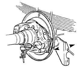
NOTE
To carry out the following inspection procedure the camshaft, brake spider, air chamber
bracket, and slack adjuster including normally used shim washers must be assembled as
shown.
(7)
Check camshaft end play as detailed in
steps 8 thru 11 following
(8)
Mount a suitable dial indicator with the
plunger referencing the cam head at 90
deg. from cam face.
(9) Pull camshaft inward, ie., cam head toward
spider, to take up any end play and set dial
indicator to zero.
(10)
Push camshaft outward and note maximum
dial indication. The end play measured
should be 0.005 - 0.045 in. (0.13 - 1.14
mm).
4-571
|