|
| |
TM 5-4210-220-12
4-30. REAR AXLE - Continued
4-30.4 Brake Assembly - Continued
(7)
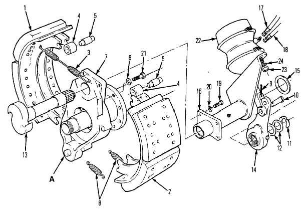
Removesnap ring (11) and washers (12) from camshaft (13)
(8)
Remove slack adjuster (14) using a suitable puller
CAUTION
Do not hammer on slack adjuster to remove. Damage to slack adjuster and/or camshaft (13)
splines may result.
(9)
Remove washer (15) and pull camshaft (13) out of air chamber bracket (16)
(10)
Tag and disconnect brake chamber air lines (17 and 18)
(11) Remove capscrews (19) and washers (20) attaching air chamber bracket (16) to brake spider (7)
and remove air chamber bracket
(12) Inspect brake spider (7) for cracks at bolt hole, cam area or around anchor pin. Remove capscrews
(21) and washers (6) if replacement is required.
(13) Inspect air chamber bracket for cracks or bends. Inspect air chamber for leaks, bent push rod, loose
clamp rings, clogged vent holes or housing damage. Replace either component by removing nuts (23)
and washers (24).
4-570
|