|
| |
TM 5-4210-220-12
4-28. ENGINE - Continued
(4)
Pull
bearing
cap
into
position
be
alternately tightening the four attaching
bolts. Torque to 120 in. lb (14 Nm).
n.
Cylinder Block Installation.
(1)
Place a new cylinder block to crankcase
gasket (4) on the crankcase (5). Place
the cylinder block (3) on the crankcase in
the same orientation as it was removed.
(2)
Assemble
the
six
bolts
(1)
and
lockwashers (2) torquing the two center
bolts to 8 ft lb (11 Nm), then the four end
bolts. Increase the bolt torque to 30 ft lb
(41 Nm), torquing the center two bolts and
then the four end bolts.
p.
Piston and Connecting Rod Assembly
(1)
Position connecting rod in piston and
press piston pin into place. This may be a
slip fit or light press fit.
(2)
Install snap rings into piston at the ends of
the piston pin.
NOTE
Compression
rings
must
be
installed
with
surface
marked
"TOP" facing top of the piston.
Some compression rings may
have dots indicating the top of the
ring.
(3)
Install compression and oil rails and expander rings on pistons. Seven rings are used in each piston, two
compression rings in each of the top two grooves, and two oil rails and an expander ring at the bottom.
(4)
Stagger ring gaps by 120 deg.
(5)
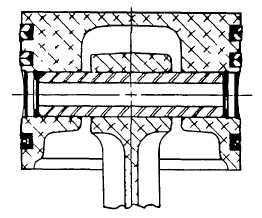
Press the connecting rod bearing inserts into the connecting rod and bearing cap. Make sure the
locating tangs on the inserts engage the locating notches in the rod and cap. Aline arrows on the cap
and rod as shown. Make sure each rod cap is installed on the rod from which it was removed.
(6)
Coat rod bearings with engine oil (item 17, Appendix E).
4-547
|