|
| |
TM 5-4210-220-12
4-27. TRANSMISSION - Continued
4-27.2 Transmission and Flexplate
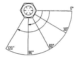
(21) Tighten retaining bolts (1) to 50 ft lb (68
Nm). Turn the bolts an additional 90 -
120 deg. to obtain required clamping
force.
(22) Tighten flexplate assembly bolts (8) to
115 ft lb (156 Nm).
(23) Remove bolts installed to align flexplates.
(24) Position transmission on transmission lift
stand and push stand and transmission
under truck.
(25) Apply gasket eliminator (item 14,
Appendix
E)
to
transmission/engine
flange. Raise and align transmission to
engine.
NOTE
Installing two alignment dowels in engine flywheel housing will help during installation of
transmission to engine. Dowels should be 7/16 in. - 20 X 6 in. long.
CAUTION
Do not pull transmission and engine together with flywheel housing bolts. Damage to flywheel
pilot and crankshaft could result. Transmission and engine must be pushed completely together
before tightening bolts.
(26) With transmission flush and square with engine flywheel housing, install 24 bolts attaching transmission
to engine.
(27) Tighten bolts to 65 ft lb (88 Nm).
(28) Install 12 bolts through starter hole opening, to attach flexplate to flywheel. Use engine barring tool
J22582 to rotate engine and transmission to install all bolts. Tighten to 115 ft lb (156 Nm). When all
bolts have been tightened remove barring tool.
(29) Check isolators are in place and undamaged on frame brackets. Install transmission support brackets
to frame. Install mounting brackets to transmission. Align transmission and frame mounting brackets
using mounting bolts as guides and by raising/lowering the engine support bracket (4, Appendix G)
adjusting bolts. Install snubbing washers and new locknuts and tighten to 170 ft lb (231 Nm).
(30) Remove engine support brackets (4, Appendix G).
(31) Install transmission dipstick to transmission pan.
(32) Install transmission dipstick upper support and bracket to transmission.
4-526
|