|
| |
TM 5-4210-220-12
4-27. TRANSMISSION - Continued
(6) Remove mounting bracket from transmission and mounting brackets from frame.
(7) Remove steering pump support bracket (1) from right side of the engine. Lift steering pump and
bracket out of the way and secure with mechanics wire.
(8) Install engine support brackets (4, Appendix G) to rear side of engine pads on engine flywheel housing.
Attach brackets with 5/8 - 11 X 1 1/2 in. bolts, 6 each side. Adjust bracket adjusting bolts until rear of
engine is supported by frame.
(9) Remove floor jack from transmission.
(10) Position transmission lifting stand under transmission. Attach support brackets and safety chains.
Adjust height and angle to properly support transmission.
(11) Using removed starter mounting hole as an access hole, remove 12 bolts attaching flexplate to
transmission flywheel. Barr engine with J22582 to remove flexplate bolts.
(12) Remove inspection plate from top left hand of torque converter housing. Remove 24 bolts attaching
transmission housing to engine flywheel housing, three bolts are accessed through the torque
converter housing inspection plate.
(13) Pry transmission rearward from engine flywheel housing. Continue to move transmission rearward until
it can be lowered clear of engine.
(14) Remove transmission and lifting stand from underneath truck.
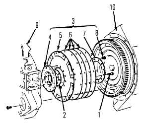
(15) Remove flexplate assembly from engine
crankshaft by removing six bolts (1) and
retaining plate (2). Remove flexplate
assembly (3).
(16) Remove retaining bolts (8) from hub (4).
(17) Separate drive discs (5 and 6). Check for
cracked centers or damaged exterior
mounting holes. Replace any damaged
plates.
(18) Assemble flexplate hub (4), drive disc (5
and 6), retainer (7), and retaining bolts
(8). Do not tighten bolts.
(19) Apply antiseize (item 4, Appendix E) to
bolts (1). Align flexplate assembly and
retaining plate (2) on crankshaft and
install bolts (1). Do not tighten bolts.
(20) Align flex discs by installing two 1/2 in. nuts and bolts on outer circumference of disc assembly 180 deg.
apart. Tighten to hold in position.
4-525
|