|
| |
TM 5-4210-220-12
4-26. DRIVE LINES, POWER TRAIN - Continued
4-26.3 Drive Shafts - Continued
a.
Drive Shaft Installation - Continued.
(3)
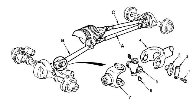
Maneuver the universal joint (5) into yoke so that cross journals are positioned in yoke lugs (6).
(4)
Install bearing plate (3). Push journal of cross (5) through the yoke lugs (6) and into needle bearing in
bearing plate.
(5)
While supporting the cross, to prevent separation of cross and bearing, use a hammer, and with the cross
alined, lightly tap bearing plate (3) until it is completely installed.
(6)
Install lockstrap and finger tighten both capscrews.
(7)
Rotate drive shaft and yoke one half turn to facilitate installation of the second bearing plate.
(8)
Carefully install bearing plate onto the opposite arm of the cross.
(9)
Install lockstrap and finger tighten both capscrews.
(10)
Repeat step 1 at other end of drive shaft.
(11)
Install the second universal joint. Repeat procedure detailed in step 3 thru 9.
(12)
Tighten all capscrews (1) to 40 ft lb (54 Nm).
(13)
Secure capscrews by bending up jockstrap tabs.
4-508
|