|
| |
TM 5-4210-220-12
4-24. ELECTRICAL SYSTEM - Continued
(28)
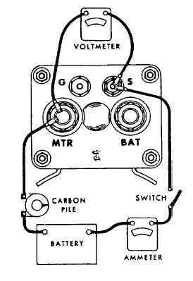
Repeat test with connections shown. This tests the pull-in winding of the solenoid. Replace solenoid if any
faults are indicated
(29)
Install armature into the nose housing bearing and check play between armature and bushing. If play is
excessive replace bushing. Dip bushing into lubricating oil (item 17, Appendix E) prior to installation. (Use
SAE No. 20 oil).
(30)
Repeat above for the commutator end plate bushing.
(31)
Repeat above for the drive housing bushing.
(32)
Inspect lever and lever housing. Ensure fork moves freely on its fulcrum pin. Be sure tabs on fork are not
worn. Replace any components failing inspection.
(33)
Install new O-ring on lever housing, field frame end.
(34)
Install armature in lever housing. Install brake washer over protruding armature shaft.
(35)
Slide drive assembly onto armature shaft. Withdraw shaft until drive assembly locates on fork
(36)
Install and tighten lever housing retaining screws.
(37)
With brush assembly attached to end frame, pull armature out of the field frame just far enough to permit
the brushes to be placed over the commutator.
(38)
Install new O-ring on end frame and install end frame over field frame.
(39)
Install and tighten end frame screws and lockwashers.
(40)
Install new gasket in lever housing and install nose housing onto lever housing. Be sure the housings are
alined as noted during disassembly.
4-421
|

