|
| |
TM 5-4210-220-12
4-24. ELECTRICAL SYSTEM - Continued
4-24.2 Starting Motor - Continued
(7)
Low speed and low current indicates:
(a)
high internal resistance due to poor connection, defective leads, or dirty commutator
(b)
same faults as step 6 preceding.
(8)
High speed and high current indicate shorted fields.
(9)
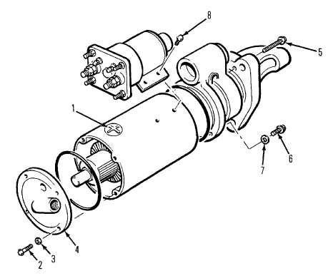
To disassemble the motor, note the relative positions of the solenoid, lever housing, and nose housing.
Mark pieces with chalk to ensure motor is assembled in the same manner.
(10)
Disconnect motor from test gear (if necessary) and disconnect field coil connector from solenoid MTR
terminal.
(11)
Disconnect lead between solenoid and motor ground terminals. Remove screws (8) from solenoid.
Remove brush inspection plugs (1) and the brush lead screws.
(12)
Remove bolts (2) and washers (3) and separate end frame (4) from field frame.
(13)
Remove bolts (5) and separate nose housing from lever housing.
(14)
Remove bolts (6) and washers (7) and remove lever housing from field frame.
4-418
|