|
| |
TM 5-4210-220-12
4-24. ELECTRICAL SYSTEM - Continued
(4)
Reconnect batteries.
(5)
Press cab START button, with ignition ON. Be sure main engine cranks at good speed and when button is
released, starter motor disengages. A distinct pull-in of the solenoid will be heard just prior to the motor
starting.
REPAIR
NOTE
Starting motor must be removed from truck prior to repair. When repairing, only disassemble motor so far as is
necessary to make repair or replace defective parts.
(1)
Check armature rotates freely by prying pinion with a screwdriver. If the armature does not turn freely,
disassemble starter to find cause (see step 9 following). Otherwise proceed with tests 2-8.
(2)
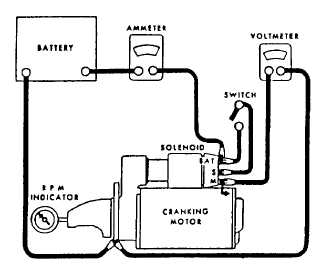
Connect starter motor to test gear as shown. Be sure battery is fully charged.
(3)
Close switch and note the reading on the voltmeter, ammeter and rpm indicator. At a voltage of between
10 and 13 volts, a healthy motor will have a current draw of between 140 - 215A at a speed of 4000 - 7000
rpm.
(4)
Low speed and high current indicates.
(a)
tight, dirty, or worn bearings
(b)
loose pole shoes
(c)
bent armature shaft
(d)
shorted armature
(e)
grounded armature or field
(5)
No speed and high current indicates:
(a)
direct ground in terminal or fields
(b)
seized bearings
(6)
No speed and no current draw indicates:
(a)
open field circuit
(b)
open armature coils
(c)
broken brush springs, worn brushes, high insulation between commutator bars or other causes
preventing good contact between brushes and commutator
4-417
|