|
| |
TM 5-4210-220-12
1-15. DRIVE TRAIN. - Continued
b. Controlled Traction Differential. The front and rear axles are both provided with Controlled Traction
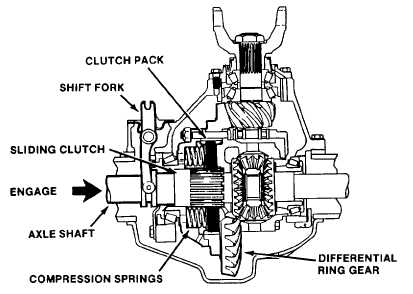
Differentials (differential locks). The differential locks, (see fig. 1-26) incorporate a friction plate assembly (clutch) which
is under constant spring pressure. When engaged, the differential lock prevents one wheel from slipping in relation to the
other on the same axle. When disengaged, conventional differential action for normal road conditions is restored. When
engaged, the differential lock will slip sufficiently for the vehicle to negotiate turns in a normal manner.
Figure 1-26. Controlled Traction Differential Clutch
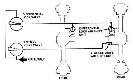
c. Power Divider and Differential Lock Control. Four-wheel-drive and the differential locks are engaged and
disengaged by air-operated shift units, (see fig. 1-27). Air flow to these units is controlled via two selector valves in the
cab. The four wheel drive shift unit should be engaged only when the vehicle is stopped or driven at very low speed.
The differential locks can be actuated at any time except when one or more wheels are spinning.
Figure 1-27. Differential Lock And Four Wheel Drive Systems
1-33
|