|
| |
TM 5-4210-220-12
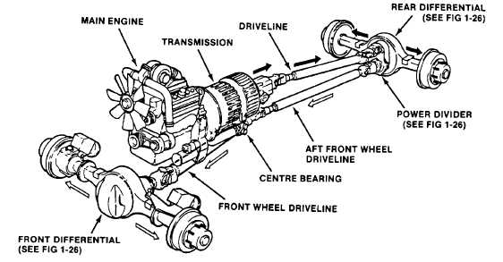
1-15. DRIVE TRAIN. Tractive power from the engine is transferred via the transmission and main drive line through the
power divider and rear differential to the rear wheels, (see fig. 1-24). Power transfer to the front wheels is provided via
the power divider and front wheel drive lines.
Figure 1-24. Tractive Power transfer
a. Power Divider.
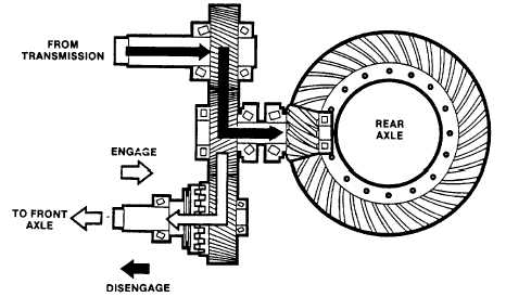
(1) The 4-wheel drive transfer gearing and the power flow through the power divider is illustrated in figure 1-
25. The transfer gearing includes a mechanical sliding clutch for engagement and disengagement of the drive line to the
front wheels.
(2) In two-wheel operating mode, the sliding clutch is disengaged and power flow is direct to the rear axle.
For four-wheel-drive operation, the sliding clutch is engaged and power is distributed through the helical gears to both the
front and rear axles.
Figure 1-25. Power Divider Operation
1-32
|