|
| |
TM 5-4210-220-12
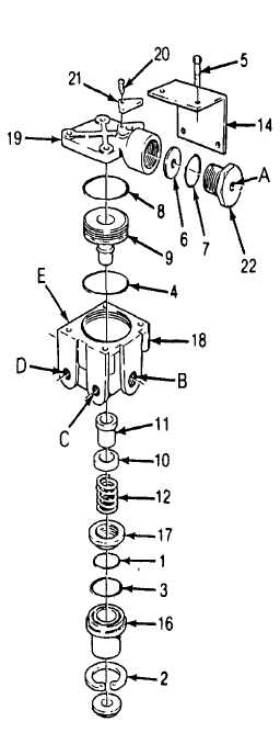
4-22. AIR SYSTEM - Continued
4-22.4. Relay Valve - Continued
(9)
Remove the screw (20) and exhaust cover
(21) from the cover
(10) Remove the service port cap nut (22) and
O-ring (7) from the cover
(11) Remove the diaphragm (6) from the cover
(12) Discard all parts except body (18), cover
(19), cap nut (22) mounting bracket, relay
piston (9), and capscrews
(13) Clean all remaining parts and Inspect for
excessive
wear,
scrub
marks
or
deterioration. Inspect the valve seat for
nicks or burrs. Replace any parts failing
inspection.
(14) Lubricate all new O-rings, O-ring grooves,
and piston bores with petroleum jelly (item
21, Appendix E).
(15) Install large piston O-ring (4) on piston (9)
(16) Install inner (1) and outer (3) O-rings in the
exhaust cover assembly and install retainer
(17)
(17) Install the O-ring (8) on the cover
(18) Install piston in body, taking care not to
damage the piston O-ring.
(19) Noting the reference marks made during
disassembly, install the cover on the valve
body and the mounting bracket on the
cover.
(20) Secure the mounting bracket and cover to
the body using the four capscrews (5) and
lockwashers. Torque to 80 - 120 in. lb (9 03
- 13 55 Nm)
(21) Install the valve retainer (10) In the
inlet/exhaust valve (11) and install in the
body.
(22)
Install the inlet/exhaust valve return spring (12) in the body
(23)
Install the exhaust cover assembly in the body taking care not to damage the O-ring
(24)
While depressing the exhaust cover, install retaining ring (2) Make sure the retaining ring is completely
seated in its groove in the body.
4-350
|