|
| |
TM 5-4210-220-12
4-22. AIR SYSTEM - Continued
(5)
When all air tanks are at pressure, make several brake applications and check for prompt application and
release of the rear brakes
(6)
With the service brakes released, brush the exhaust port and area around the retaining ring with soap
solution A 1 in. (2.5 cm) bubble in 3 seconds leakage is permitted
(7)
With the service brakes applied, brush the exhaust port with soap solution. A 1 in. (2.5 cm) bubble In 3
seconds leakage is permitted.
(8)
With the service brakes applied, brush the outside of the valve, where the cover joins the body, and each
hose connector with soap solution. No leakage is permitted.
(9)
If the body or a connector leaks, tighten or remake connections as required. If the exhaust port leaks,
repair the valve as detailed in REPAIR following.
REPAIR
NOTE
The relay valve can only be
repaired if it is removed from the
truck. See REMOVAL preceding.
Prior to disassembly, mark the
location of the mounting bracket to
the cover and the cover to the
body.
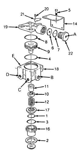
(1)
Remove the four capscrews (5) and
lockwashers securing the cover (19) to the
body
(2)
Remove the cover (19), ring (8), and
mounting bracket (14)
(3)
Remove the piston (9) and O-ring (4) from
the body (18)
(4)
While depressing the exhaust cover (16),
remove the retaining ring (2, 8) and slowly
relax the spring (12) beneath the exhaust
cover
(5)
Remove the exhaust cover assembly.
Remove O-ring retainer (17) from exhaust
cover and remove O-rings (1 and 3)
(6)
Remove the inlet/exhaust valve return
spring (12) from the body
(7)
Remove the inlet/exhaust valve (11) from
the body
(8)
Remove the valve retainer (10) from the
inlet/exhaust valve
4-349
|

