|
| |
TM 5-4210-220-12
4-22 AIR SYSTEM - Continued
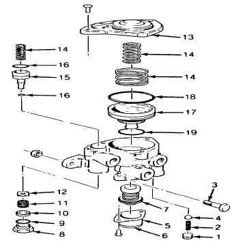
4-22.3 Spring Brake Valve - Continued
(8)
Remove the four screws and lockwashers that
secure the cover to the body
(9)
Remove the cover (13) and the three piston
springs (14)
NOTE
Some spring brake valves have only two piston
springs.
(10) Remove the small piston (15) and the small and
large O-rings (16)
(11)
Remove the large piston (17) Remove piston
O-rings (18) and (19)
(12) Discard all parts except cover (13), piston (17),
pipe plug (1), exhaust cover (5), cap nut (8),
piston (15), machine screws and body
(13) Clean all remaining parts and inspect for
excessive wear, scrub marks or deterioration.
Inspect the valve seats for nicks or burrs.
Replace any parts failing inspection.
(14) Lubricate all new O-rings, O-ring grooves, and
piston bores with petroleum jelly (item 21,
Appendix E)
(15) Assemble the check valve (4), and valve spring (2) and install in body
(16) Apply pipe sealant (item 22, Appendix E) to the socket head pipe plug (1) and install In the body. Tighten
to 130 - 170 in. lb (14.6 - 19.3 Nm)
(17) Install inlet and exhaust valve assembly (7) in valve body
(18) Secure the exhaust cover (5) with the two screws and lockwashers. Tighten to 20 - 30 in. lb (2.25 -
3.38 Nm)
(19) Install exhaust diaphragm (6) into the exhaust cover
(20) Place inlet exhaust valve (12) in the body. Install the valve spring (11) and valve stop (10)
(21) Install 0-ring (9) on cap nut and install cap nut (8) in body. Tighten to 100 - 125 in. lb (11.3 - 14.1 Nm)
(22) Install the small and large O-rings (16) on the small diameter piston (15) and install piston in the body
4-346
|