|
| |
TM 5-4210-220-12
4-22. AIR SYSTEM - Continued
(4)
Connect truck batteries and start main engine. When air system is pressurized, release the parking
brakes
(5)
Check all connections for leaks using a brush and soap solution. Tighten as required.
(6)
When brakes are released, pressure gage on inlet port should read at least 65 psi (450 kPa)
(7)
Place parking brake in the PARK position. Be sure the spring brakes on the rear wheels apply promptly
and pressure reading drops quickly to zero. When set to RELEASE, be sure brakes release promptly.
(8)
Open the primary reservoir draincock and allow it to drain. Apply the foot brake several times and note
the gage pressure reading. Check that the pressure drops continuously and the parking brakes do not
release after some more attempts.
(9)
Shut down main engine and drain all air tanks
(10)
Remove gage and tee from spring brake valve. Replace with the original elbow.
(11)
Repressurize all air tanks with main engine and check brakes on moving vehicle
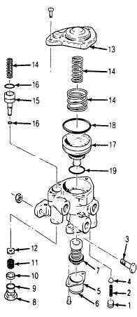
REPAIR
NOTE
The spring brake valve can only be repaired if it is removed from the truck. See REMOVAL
preceding.
(1)
Remove the socket head pipe plug (1)
(2)
Remove the check valve spring (2) and the check
valve (4)
(3)
Remove the two screws and exhaust cover (5)
(4)
Separate the exhaust diaphragm (6) from the cover
(5)
Remove the inlet and exhaust valve assembly (7)
(6)
Remove the inlet and exhaust valve cap nut (8)
and separate the cap nut O-ring (9)
(7)
Remove the valve stop (10), valve spring (1 1), and inlet
and exhaust valve (12)
CAUTION
The cover is under a spring load, and should be held
while removing the screws.
4-345
|