|
| |
TM 5-4210-220-12
4-18. PUMP, PIPING, AND VALVES - Continued
4-18 17 Bumper Turret - Continued
a. Handle Repair - Continued
(8) Evidence of damage of any kind is cause
for rejection. Replace parts as necessary.
(9) Install handle (5) into handle holder (7).
Align roll pin holes and insert roll pin (6).
(10) Raise handle into position. Align handle
holder holes with the holes in the column
link (9) and swivel block (8) and install
studs (2 and 3).
(11) Install new locknuts (1) onto studs (2 and
3) and tighten to 17 ft lb (23 Nm).
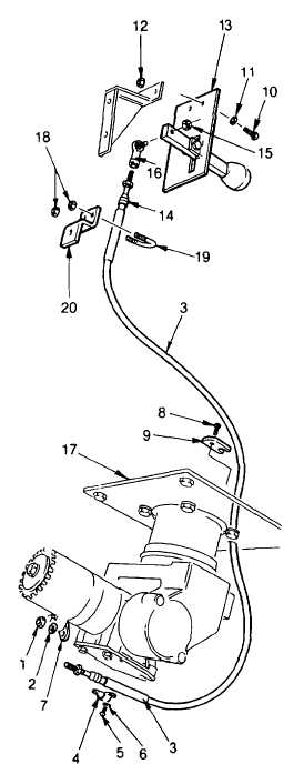
b. Control Cable Repair
NOTE
This task can be completed with the
turret mounted on the truck. Control
cable
repair
consists
of
cable
replacement if cable does not function
freely.
(1) Remove nut (1) and lockwasher (2) from
nozzle end of cable (3).
(2) Remove conduit clamp (4) that holds cable
(3) to the mounting plate (7) by removing
screws (5) and lockwasher (6).
(3) Pull cable (3) out of water sleeve link (8).
(4) Remove capscrew (9) and lockwasher that
retains clamp (10) Pull clamp off cable (3).
(5) Remove screws (11), lockwashers (12),
and nuts (13) that retain the handle bracket
(14) to the pattern control bracket.
(6) Loosen jam nut (16) and unscrew the ball
joint (17) from the cable end rod (15).
Count the number of turns it takes to
remove ball joint and record.
(7) Remove locknuts (20) from U-bolt (21) and
remove cable (3) from Z-plate (22).
(8) Pull cable (3) through base plate (18) to
remove.
4-278
|