|
| |
TM 5-4210-220-12
1-11. ENGINE AIR INTAKE AND EXHAUST SYSTEMS. - Continued
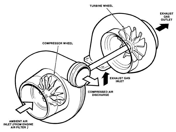
b. Turbocharger The turbocharger compressor wheel and turbine are mounted on a common shaft but located
in isolated housings, (see fig. 1-18). The turbine wheel, driven by the hot exhaust gases, drives the compressor wheel.
Air from the filter is drawn into the compressor, pressurized, and discharged to the engine blower.
Figure 1-18. Turbocharger
c. Engine Blower. Second stage compression of the intake air is accomplished by an engine blower. This blower
and the turbocharger work in conjunction. At low engine speed, little compression takes place in the turbocharger.
Therefore, primary pressurization of the intake air takes place in the blower unit. At higher engine speeds, the
compression capacity of the turbocharger exceeds that of the engine blower and most of the air from the turbocharger is
discharged directly into the aftercooler via a by-pass valve in the blower housing.
d. Exhaust System. After combustion, the hot exhaust gasses flow from the engine through the exhaust manifold
and turbocharger. From the turbocharger, the exhaust is vented to atmosphere through the exhaust pipe and muffler.
1-25
|