|
| |
TM 5-4210-220-12
Section III. TECHNICAL PRINCIPLES OF OPERATION.
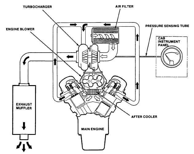
1-11. ENGINE AIR INTAKE AND EXHAUST SYSTEMS The flow of engine intake air and exhaust gases is shown in
figure 1-17.
a. Air Filter and Duct. Air for combustion is drawn through the air filter which removes dust particles harmful to
the engine. The filter element and housing are permanently bonded together to prevent by-pass of unfiltered air. From
the filter, the air is ducted to the turbocharger. The duct, consisting of a flexible elbow, is clamped to the filter housing
and turbocharger. A sensor tube is connected from the elbow duct to a pressure gage located in the cab. As dust and
other airborne particles are trapped, restriction to flow through the element increases and results in a lower pressure in
the duct. This pressure is registered on the gage and used as a filter condition indicator.
Figure 1-17. Engine Intake Air and Exhaust Gas Flow
1-24
|

