|
| |
TM 5-4210-220-12
4-18. PUMP, PIPING, AND VALVES - Continued
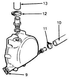
(11) Install the primer inlet hose (10) onto the
primer inlet connection and tighten the gear
clamp (11).
(12) Install the primer return hose (13) onto the
primer inlet connection and tighten the gear
clamp (12).
(13) Tighten the suction tee capscrews (1) to 270
ft lb (365 Nm).
(14) Tighten the pump discharge elbow locknuts
(6) to 150 ft lb (205 Nm).
(15) Wipe off excess gasket eliminator (Item 2,
Appendix E) from pipe flanges.
(16) Raise the pump suction bracket into
position and attach pipe clamp to suction
pipe. Install outermost capscrews through
pump, pump bracket and suction pipe
bracket. Tighten capscrews and nuts to
270 ft lb (266 Nm). Tighten pipe clamp
securely.
(17) Allow gasket eliminator to cure for at least one hour prior to testing for leaks.
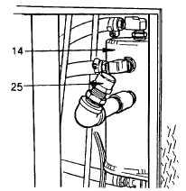
(18) Ensure the drain valve (9) on the priming pump housing is closed. Fill the pump primer reservoir (14)
with antifreeze (item 2, Appendix E) through the reservoir fill tube (25).
(19) Check the fire pump oil level (see Lube Order LO 5-4210-220-12)
(20) Install box rear plate (C).
(21) Install all equipment in compartment box.
(22) Install reducer gear to pump drive shaft as
detailed in para. 4-17.3.
(23) Fill tank and start fire pump as detailed in
para. 2-11 and check for any leaks.
Tighten/remake joints as required.
(24) Replace heat shields as detailed in para. 4-
11.2 and para. 4-11.3.
4-219
|


