|
| |
TM 5-4210-220-12
4-18. PUMP, PIPING, AND VALVES - Continued
4-18.1 Fire Pump - Continued
INSTALLATION
WARNING
Serious injury could occur if heavy equipment is moved/lifted without sufficient personnel to do the
job. Use proper physical lifting procedures or use a suitable lifting device or dolly. Wear safety
shoes, gloves and other suitable protective clothing.
(1) Be sure the suction tube, the volute body
and their mating surfaces are clean prior to
re-gasketing.
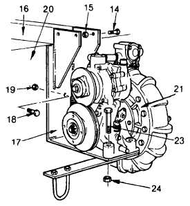
(2) Set the pump (21) on the pump mounting
bracket (17) and align the mounting holes.
(3) Install the two innermost capscrews (23) and
new locknuts (24) and tighten to 270 ft lb
(266 Nm).
(4) Lift the pump and bracket assembly off the
workbench and set it on the saddle of a
dolly type hydraulic jack.
(5) Apply gasket eliminator (Item 14, Appendix
E) to the volute body and suction tube
flanges.
(6) Carefully raise the dolly type hydraulic jack
until the mounting holes in the pump
mounting bracket (17) align with the holes
in the mounting channel (16). Align the
suction tube and volute body flanges with
their
respective
piping
and
install
capscrews and locknuts fingertight.
(7) Install the four capscrews (14) and new
locknuts (15) used to fasten the pump
mounting bracket (17) to the mounting
channel (16). Tighten the locknuts to 160
ft lb (217 Nm).
(8) Align the mounting holes in the pump mounting bracket (17) with the holes in the frame side member (20).
(9) Install the four capscrews (18) and new locknuts (19) used to fasten the pump bracket (17) to the frame
side member (20). Tighten the locknuts to 160 ft lb (217 Nm).
(10) Remove the block of wood used to support the mounting channel during pump removal.
4-218
|