|
| |
TM 5-4210-220-12
4-17. PUMP DRIVE AND PTO - Continued
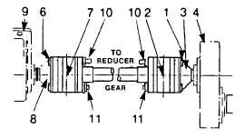
(5) Using a soft hammer, lightly tap spacer plate (5) until the constant velocity joint (7) separates from the
companion flange (8).
(6) Carefully maneuver the PTO to reducer gearbox drive shaft out from between the PTO (9) and the reducer
gear (4).
INSTALLATION
(1) Apply gasket eliminator (item 14, Appendix E) to the mating surfaces to the PTO and reducer gear
companion flanges (3, 8).
(2) Raise the PTO to reducer gear drive shaft into position.
(3) Support PTO end of drive shaft using mechanics wire.
(4) Align mounting holes of the constant velocity joint (2) with the holes in the companion flange (3). Install
capscrews (1) fingertight.
(5) Align mounting holes of the constant
velocity joint (7) with the holes in the
companion flange (8). Install capscrews (6)
fingertight.
(6) Torque all drive shaft capscrews (1 and 6)
to 63 ft lb (85 Nm).
(7) Remove mechanics wire used as a support.
(8) Lubricate both constant velocity joints.
Remove plug (11) from the inboard side of
the constant velocity joint. Cover this hole
with your finger. Lubricate constant velocity
joint through grease fitting (10) until grease
(item 16, Appendix E) is expelled from hole.
Reinstall plug (11) into hole and tighten.
4-209
|

