|
| |
TM 5-4210-220-12
4-15. AUXILIARY POWER UNIT - Continued
(13)
Place piston at top dead center..
(14)
Insert the camshaft with cams on
overlapping position (inlet starts to open-
exhaust just about to close). Check that
tappets are at the same height, otherwise
shift gear one tooth back or forward until
alinement of tappets is obtained.
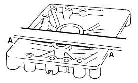
(15)
Lay straight edge across inside of
crankcase cover. The gasket surface of
housing should be on same plain as the
cover thrust surface for the crankshaft.
There should be no clearance at A.
Check with feeler gage. If there is
clearance, measure with feeler gage.
(16)
Support
engine
on
workbench
so
crankshaft and camshaft are positioned in
upright position.
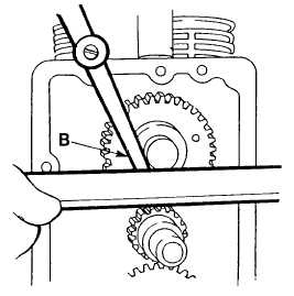
(17)
Measure clearance B between straight
edge placed across block and thrust
surface of camshaft. Clearance B should
not be greater than 0.004 in. (0.10 mm).
(If
necessary
combine
clearance
measurements A and B).
(18) Select gasket(s) to give camshaft end play
of 0.004 - 0.012 in. (0.10 - 0.30 mm).
Gaskets are available in. 0.008, 0.012 in.
(0.20, 0.30 mm) sizes.
(19)
Coat crankshaft cover camshaft journal,
crankshaft needle bearing, and oil seal
with lubricating oil (item 17, Appendix E).
(20)
Install crankshaft cover using machine
screws. Be sure engine breather tube
clamp is installed with bottom left hand
screw.
4-181
|