|
| |
TM 5-4210-220-12
4-15. AUXILIARY POWER UNIT - Continued
4-15.10 Engine Piston and Piston Rod - Continued
(10)
Remove rings with expander and scrape away
all carbon deposits from ring grooves (Use
discarded ring if required).
(11)
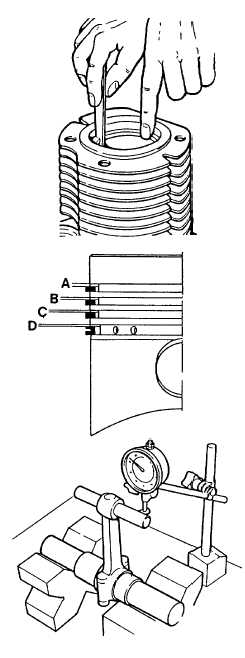
Install new rings in cylinder and check for
perfect mating between ring and cylinder wall.
Measure ring end gap. File ring ends as
required.
End gap for compression ring should be 0.010 -
0.016 in. (0.25 - 0.40 mm), for oil control ring,
0.008 - 0.014 in. (0.20 - 0.30 mm).
(12)
Install rings on piston and measure ring to
groove clearance. Top ring is chromium plated.
Replace piston and/or rings if wear limit
exceeds that shown.
WEAR LIMITS
A
0.009 in. (0.22 mm)
B
0.007 in. (0.17 mm)
C
0.007 in. (0.17 mm)
D
0.005 in. (0.12 mm)
(13)
Check alinement of piston rod bores as
illustrated. Replace if bending or twist exceeds
0.002 in. (0.05 mm). Bend or twist may be
straightened in press if less than this figure.
(14)
Measure crankshaft journal for wear. If wear
exceeds 0.004 in. (0.10 mm), regrind crankshaft
and fit undersize bearings, see para. 4-15.12.
Crank pin diameter is nominally 1.5756 - 1.5760
in. (39.9 - 40.00 mm), 1st undersize is 1.5658 -
1.5662 in. (39.74 - 39.75 mm), 2nd undersize is
1.5560 - 1.5563 in. (39.745 - 39.755 mm)
INSTALLATION
(1)
Ensure piston ring gaps are 180 deg. apart.
(2)
Swab cylinder and piston with lubricating oil (item 17, Appendix E).
(3)
Install piston rod in piston, slide piston pin into piston and secure with retaining ring.
4-172
|

