|
| |
TM 5-4210-220-12
4-15. AUXILIARY POWER UNIT - Continued
(7)
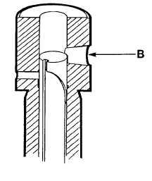
Continue to rotate until fuel stops spilling. This is the start of the pumping stroke. Injector pump plunger is
covering barrel feed orifice B.
(8)
Note position of dial injector (method 1) Dial gage must indicate a prestroke of 0.084 - 0.092 in.
(2.10 - 2.30 mm).
(9)
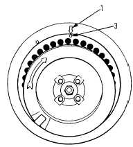
Note position of flywheel timing marks (both methods). Mark 3 on flywheel must be alined with mark 1 on
shroud. If fuel spilling stops earlier (timing advanced) add shims under the pump, if later (timing
retarded) remove shims.
(10)
To add or remove shims under the pump, remove pump machine screws and carefully withdraw pump.
(11)
Add or withdraw shims and replace pump in crank cover. Tighten capscrews to 20 ft lb (25 Nm).
(12)
Repeat steps 3 thru 11 as required.
(13)
If by adjusting shims, the prestroke is out of range, check camshaft (see para. 4-15.12) or repair injector
pump (see REPAIR following).
(14)
When complete, remove tester (If installed) Replace delivery valve gasket, delivery valve spring, filler
shim, delivery union and pressure line.
(15)
Set APU keyswitch OFF.
4-157
|