|
| |
TM 5-4210-220-12
4-15 AUXILIARY POWER UNIT - Continued
(2)
Install the pump mounting bracket on engine end plate using capscrews. Apply thread lock liquid (Item
29, Appendix E) to each capscrew before installing.
(3)
Install drive shaft key in key way and place sheave and bushing on engine drive shaft. Install
capscrews through bushing into sheave but do not tighten.
(4)
Mount alternator on base plate together with the belt tensioning bracket but do not tighten mounting bolts.
(5)
Install both alternator drive belts over the drive sheave and the alternator pulley.
(6)
Aline the drive sheave and drive pulley so that the belt is in the same plane.
(7)
Tighten the bushing capscrews on the engine pulley.
(8)
Pull up on alternator until drive belts are tight (less than 1/2 in. (1.2 cm) movement midway between
the pulleys) Tighten the alternator brackets, capscrews and nuts.
(9)
Install the pump drive coupling on the engine drive shaft.
(10)
Aline the pump drive coupling with the pump.
(11)
Install the capscrews, washers and nuts to attach the pump to the pump bracket.
(12)
Tighten the pump drive coupling set screws.
INSPECTION
(1)
Before installing new APU assembly in hose body ensure all shipping blanks and packaging
are removed.
(2)
Check alternator belt tension and adjust as required (Half in. (1.2 cm) movement of belt midway
between pulleys).
INSTALLATION
(1)
Using a small hydraulic floor crane or skid planks as in REMOVAL, slide APU assembly into hose
body APU compartment. Do not push all the way in.
(2)
Connect the stop control cable to engine throttle plate. Slide APU assembly into compartment
completely.
(3)
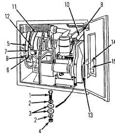
Using a pry bar, lift each corner of the base plate in turn and insert rubber washer between plate
and bottom of box.. Ensure they are alined with the hold down capscrew holes.
4-143
|

