|
| |
TM 5-4210-220-12
4-11. HEAT SHIELDS - Continued
(2)
Loosen the capscrews retaining the front heat shield (5) to the fuel tank housing (3) and battery box (4).
(3)
Leave the four corner capscrews fingertight and completely remove the rest.
(4)
While supporting the front heat shield (5), remove the four corner capscrews and lower heat shield to the
ground.
INSTALLATION
CAUTION
If drilling mounting holes in the fuel tank housing (3) or battery box (4) make sure the drill bit
does not penetrate the fuel tank or one of the batteries.
NOTE
New heat shields are supplied with the mounting holes punched. The heat shields are used as
templates to drill holes if new fuel tank housing (3) or new battery box (4) are also installed.
(1)
Apply sealant (Item 25, Appendix B) to each mating surface during assembly.
(2)
Slide the front heat shield under the truck. Raise the heat shield into place.
(3)
Install capscrews attaching the front heat shield (5) and tighten to 8 ft lb (11 Nm).
(4)
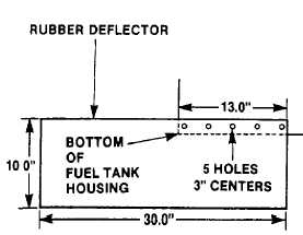
Cut and drill the rubber deflector as shown.
(5)
Lift the rubber deflector into place and aline the
holes with the insert fasteners in the fuel tank
housing.
(6)
Mark on the rubber deflector the position of the
mounting holes in the pump body and front heat
shield and where the drive shaft opening starts.
(7)
Cut and drill the rubber deflector where marked.
(8)
Install all capscrews and new locknuts and
tighten to 8 ft lb (11 Nm).
(9)
Install the left hand side rubber deflector similarly
to steps 1 thru 8 preceding.
(10)
Install pump body heat shield. Measure and drill
holes to mount lower end of rubber deflector to
pump body heat shield.
4-73
|

