 |
|||
|
|
|||
|
Page Title:
Figure 71.29. Fuel regulator valve test chart. |
|
||
| ||||||||||
|
|
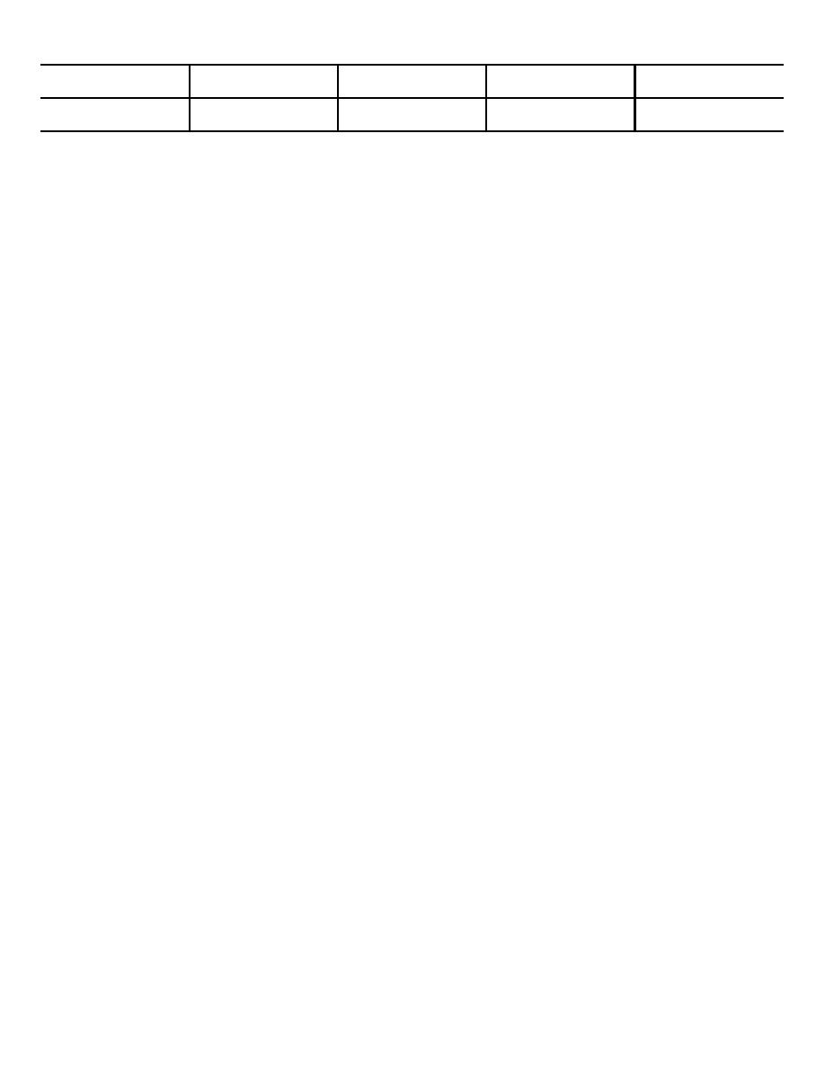 Fuel Flow
Pressure
Fuel Flow
Pressure
(cc/min.)
(psig)
(cc/min.)
(psig)
22
14.5
Minimum
28
20.2
19.5
10.15
Maximum
Figure 71.29. Fuel regulator valve test chart.
c.
Install Fuel Regulator Valve and nozzle
tee, install the adapter tee with nozzle
assembly. Connect a fuel supply capable
assembly.
of supplying a steady flow of fuel under
(1) Position the fuel regulator valve (19, fig.
constant pressure of 3 to 5 psig to the
71.28) on the control head base (20) and
regulator valve inlet port. Connect the
fasten with two screws (23). Connect
fuel tube (13, fig. 71.35) to the tee and
wires as shown in the wiring diagram (fig.
allow the fuel to flow into a measuring
71.12).
graduate (approximately 50-100 ml).
(2) Install the nozzle assembly (19, fig. 71.35)
(2)
Connect the nominal voltage power
in the adapter tee (17, fig. 71.28) and
supply to both sides of the regulator valve
insert the pipe plug (18, fig. 71.35).
and make provision to energize one or
(3) Install the elbow (18, fig. 71.28) and the
both sides of the valve.
tee on the outlet port of the fuel regulator
(3)
Operate the test setup to energize the
valve.
shut-off valve (nameplate end) of the
(4) Attach nut (16, fig. 71.35), sleeve (17) and
regulator valve and to supply fuel to the
fuel tube (15) to the adapter tee. Install
system. The fuel flow should be within
the control head assembly.
the limits shown in the fuel regulator valve
test chart below for the model heater
194. Liquid Heater Disassembly
tested. Break the circuit, and the fuel flow
(fig. 71.30).
should stop immediately.
a. Removal. Refer to figure 71.31 for removal.
(4)
Connect both sides of the regulator valve
b. Control Head Assembly Removal.
to the power supply and note the fuel flow
(1) Remove two screws (12) from the control
and pressure. The fuel flow and pressure
head cover (18) and lift cover.
should be within the limits shown in figure
(2) Disconnect ignition coil high-tension wire
71.29. Break the circuit, and the fuel flow
from
the
spark
plug
assembly.
should stop immediately.
Disconnect both primary wires leading to
(5)
If outlet pressures do not conform to
the ignition coil.
specification or fuel flow does not stop
(3) Loosen the fuel tube nuts (16) and
during test, the fuel regulator valve is
remove the fuel tube (15) and sleeves
faulty and should be replaced.
17).
(6)
If outlet pressures do conform but the fuel
(4) Disconnect at their terminal points the
flow is lower than specified during tests,
three wires extending through the
the nozzle assembly is clogged. Clean
grommet (48) in the heater casing.
the passages of the nozzle assembly with
Unscrew the flame switch mounting nut.
air. Do not attempt to clean the regulator
with any type of instrument.
(5) Remove the two wires from the limit
switch (2) and disconnect the wire
(7)
If outlet pressures do conform, but the
fuel flow is higher than specified during
tests, replace a faulty nozzle assembly.
AGO 5667A
29
|
|
Privacy Statement - Press Release - Copyright Information. - Contact Us |
