 |
|||
|
|
|||
|
Page Title:
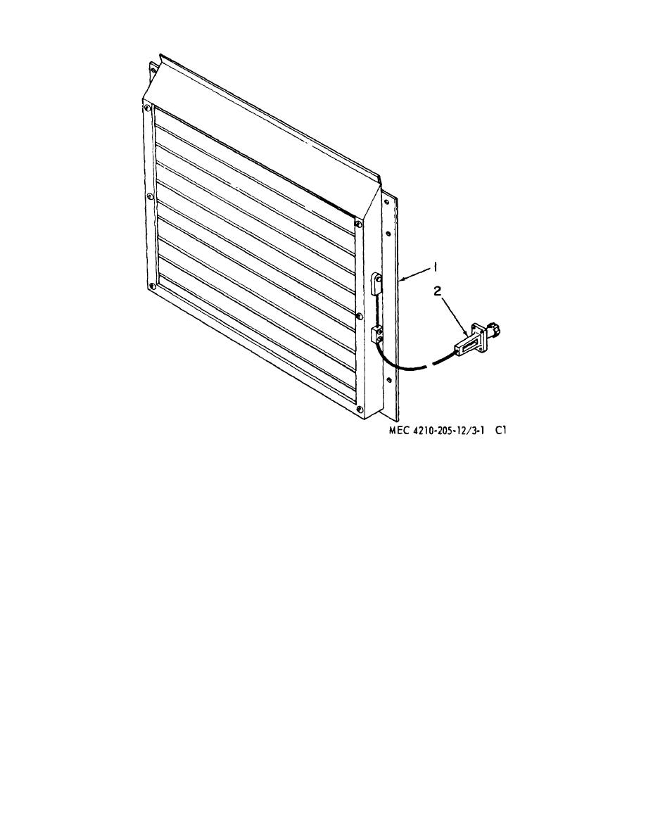
Figure 71 .21. Radiator shutter assembly. |
|
||
| ||||||||||
|
|
 1 Shutter
2 Control
Figure 71 .21. Radiator shutter assembly.
from the panel (18). Inspect the assembly visually for
the circuit breaker should open within 10
wiring defects and faulty parts. Check the circuits, using
to 125 seconds. If it fails to meet this
the wiring diagram (fig. 71.7). Replace any units that
requirement, replace the circuit breaker.
are obviously faulty. Disassemble and test the control
(3) To install the circuit breaker, position it on
box components as follows:
the pineal and fasten in place with the two
a. Circuit Breaker.
mounting screws.
Connect the leads
according to the wiring diagram (fig.
(1) To remove the circuit breaker (12, fig.
71.7.)
71.22), disconnect the electrical leads
from the terminals. Tag leads to facilitate
b.
Control Switch.
reassembly.
Remove two mounting
(1) To replace the control switch, disconnect
screws (15) from the panel (18) and
the electrical leads. Tag leads to facilitate
remove circuit breaker (12).
reassembly. Remove the mounting nut
(2) To test, connect the circuit breaker to a
from the threaded lever lug. Remove
test circuit which will supply 200 percent
rated current. Press in the reset button;
21
|
|
Privacy Statement - Press Release - Copyright Information. - Contact Us |