 |
|||
|
|
|||
|
|
|||
| ||||||||||
|
|
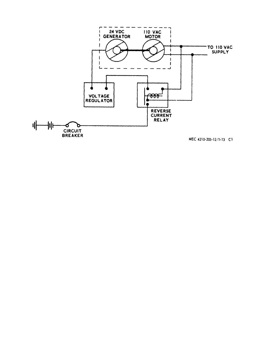
 Figure 71.13. Motor-generator set wiring diagram.
Section Ill. OPERATION
make sure power is available for operation.
163. General
If the lamp lights, power is available. If the
lamp fails to light when depressed, press the
This section of the supplement contains complete
reset button to see if the circuit breaker is
operating instructions for all components of the
tripped, and repeat the test.
winterization kit.
(2) Set the control switch to either ON position.
(When the "ON-LO" setting is used, the heat
164. Engine Radiator Shutter
output is lower than for high-fire operation.)
(3) Preheating takes place for approximately
a. Pull the control knob (fig. 71.14) outward to
one minute, after which time the ignition
close the shutters, restricting air flow through the
cycle starts. After approximately another
radiator.
minutes, the control box indicator lamp will
b. When the engine temperature gage indicates
glow and the heater will circulate warm
approximate operating temperature, push the control
liquid.
knob in to adjust the shutters in a position which allows
sufficient air flow to maintain the engine operating
Note. For one minute after the control
temperature.
switch is turned on, the heater will
c. Push the control knob fully in to open the shutter
indicate no visible or audible signs of
to maximum aperture.
operation until the preheater element
165. Liquid Heating System
heats the burner sufficiently to cause
combustion. If the control box indicator
166. Liquid Heater
lamp glows 1 1/2 to 2 minutes after
heater was turned on, the heater is
a. Starting.
operating properly.
(1) Depress the lens of the indicator lamp to
AGO 5667A
14
|
|
Privacy Statement - Press Release - Copyright Information. - Contact Us |