|
| |
TM 9-254
9-5.
Marking Optical Components.
a.
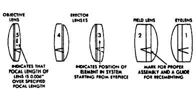
Lenses. The primary purpose for marking lenses upon disassembly is to establish a reference, so the lenses
can be assembled in their original positions in the instrument. This mark should consist of a V drawn on the unpolished
surface (edge) across all the elements of a compound lens as shown in figure 9-25. The point of the V should be pointing
towards the objective end of the instrument. All lenses of an instrument will be marked in this manner, thereby eliminating
the possibility of assembling them incorrectly. The marking of lenses can usually be done with a pencil or a magic marker.
In addition to the directional marking, the lenses will also be numbered to indicate the sequence in which they are placed in
the instrument. For example: eye lenses should be marked 1, field lenses 2, first erector 3, and so on (fig. 9-25). The
numbering system aids in preventing improper placement of the lenses which are similar in appearance and easily
mistaken for each other. In some instruments, such as the binocular, the field lens has a very thin edge which is difficult to
mark. In such cases it is necessary to note, when disassembling the instrument, whether the side of greater curvature
faces the objective lens or the eye lens, and then assemble accordingly. It is also advantageous to draw a rough sketch of
the optical system of the instrument being repaired, showing the position and relative curvature of all optical components.
This may be done as each lens is removed from the optical system. When assembling the optical components, the sketch
can be referred to for proper positioning, thus eliminating guesswork.
Figure 9-25. Lens Marking System
b.
Prisms. All markings on prisms are placed on the unpolished surfaces. In marking prisms used individually,
such as an amici or a right-angle prism, mark an arrow pointing toward the objective end of the instrument (fig. 9-26). The
marking of prisms used in pairs (fig. 9-27) such as those in binoculars is a more complex process. These prisms have
certain deviations and variations of light travel, and prism must first be marked to indicate whether it is located in the right
or left telescope of the binocular. Identify such locations by placing an R or L on each prism. Immediately after the R or L
mark and E or O. The E indicates that the prism is first in the light path of the eyepiece , whereas the O indicates that the
prism is first in the light path of the objective lens. A prism marked LE belongs in the left telescope and is first in the light
path of the eyepiece. To prevent the prisms from being assembled in a reversed position, an arrow should be drawn
pointing toward the end of the prisms where they meet on the prism assembly.
Change 2 9-18
|