 |
|||
|
|
|||
|
Page Title:
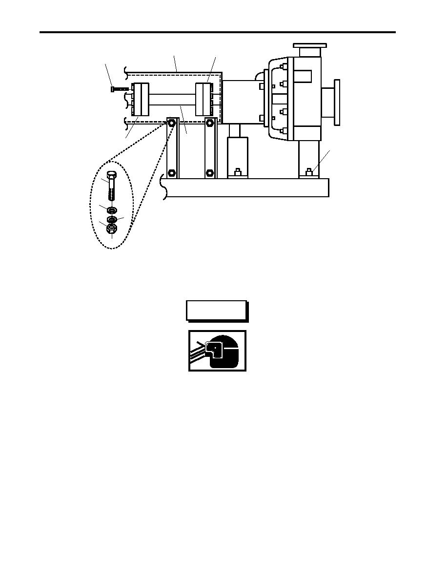
Figure 1. Firefighting Pump Alignment |
|
||
| ||||||||||
|
|
 TM 55-1925-292-14&P
0034 00
5
9
6
4
7
8
10
1
4
3
2
Figure 1. Firefighting Pump Alignment
WARNING
Removing components by means of wire brushing produces flying particles. These
particles can cause serious injury to personnel. Protective goggles, gloves, and
long sleeves must be worn at all times during wire brushing operations. Failure
to comply can result in serious injury to personnel.
5. Clean the mating faces of the PTO output flange (figure 1, item 8) and the pump input flange (figure 1, item 9)
with a wire brush, and ensure that both surfaces are clean, smooth, and free of corrosion.
6. Verify that the four pump mounting bolts (figure 1, item 10) are tight.
NOTE
The dial indicator fixing stand must be fastened to the pump input flange in order to
obtain an accurate reading. Fastening the fixing stand to the PTO output flange will
result in inaccurate readings.
7. Install the dial indicator fixing stand (figure 2, item 1) on the pump input flange (figure 2, item 2) as shown in
figure 2, to check the angular alignment.
0034 00-2
|
|
Privacy Statement - Press Release - Copyright Information. - Contact Us |
