 |
|||
|
|
|||
|
Page Title:
CONTROL MODULE CP-35 REPLACEMENT |
|
||
| ||||||||||
|
|
 TM 55-1925-292-14&P
0026 00
CONTROL MODULE CP-35 REPLACEMENT
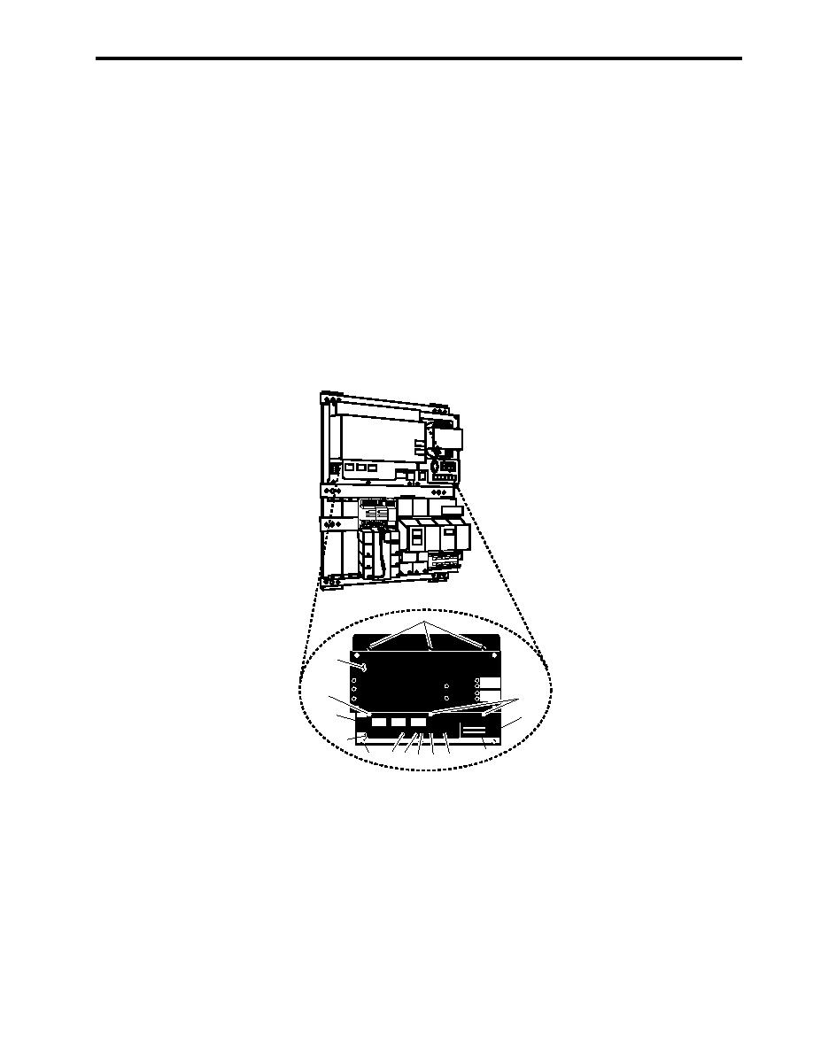
REMOVAL
1. OPEN the enclosure following the Open Enclosure procedure of this work package.
2. Remove the screws (figure 2, item 1) that secure the dust cover (figure 2, item 2) to control module CP-35
(figure 2, item 3).
3. Label and disconnect the wiring plugs from connectors P1 (figure 2, item 4), P2 (figure 2, item 5), and P3
(figure 2, item 6).
4. Label and disconnect the wiring from terminals 32 (figure 2, item 7), 35 (figure 2, item 8), and 41 (figure 2,
item 9).
5. Remove the eight screws (figure 2, item 10) that secure control module CP-35 (figure 2, item 3), and remove
it from the enclosure.
CP-35
PS 35
MM-35
BE-35
BC-35
1
TB1
2
MODELCP-35CONTROLUNIT
PFLASHERWHEN
OWING
ONBATTERY
GROUND
FAULT
AFLASRNGWHEN
LAHIM
1
System 3
SILENCED
1
AUDIBLE
TROUBLE
CIRCUIT
6
4
RESET
ALARM
TROUBLE
FUSEUNDERCOVER
LAMPTEST
SILENCE
SILENCE
CAUTIONDIEFCONNSERVPCIWGR
S
ECT O E
B ORE
I N
TBI
3
MODELCP-35
5
10 7 8 11 12 9
Figure 2. Control Module CP-35 Replacement
INSTALLATION
1. Position control module CP-35 (figure 2, item 3) into the enclosure and secure it with the eight screws (figure 2,
item 10).
2. Verify the installation of a jumper between terminals 36 (figure 2, item 11) and 39 (figure 2, item 12). Install a
jumper if one is not there.
0026 00-3
|
|
Privacy Statement - Press Release - Copyright Information. - Contact Us |
