 |
|||
|
|
|||
|
Page Title:
POWER SUPPLY PS-35 REPLACEMENT |
|
||
| ||||||||||
|
|
 TM 55-1925-292-14&P
0026 00
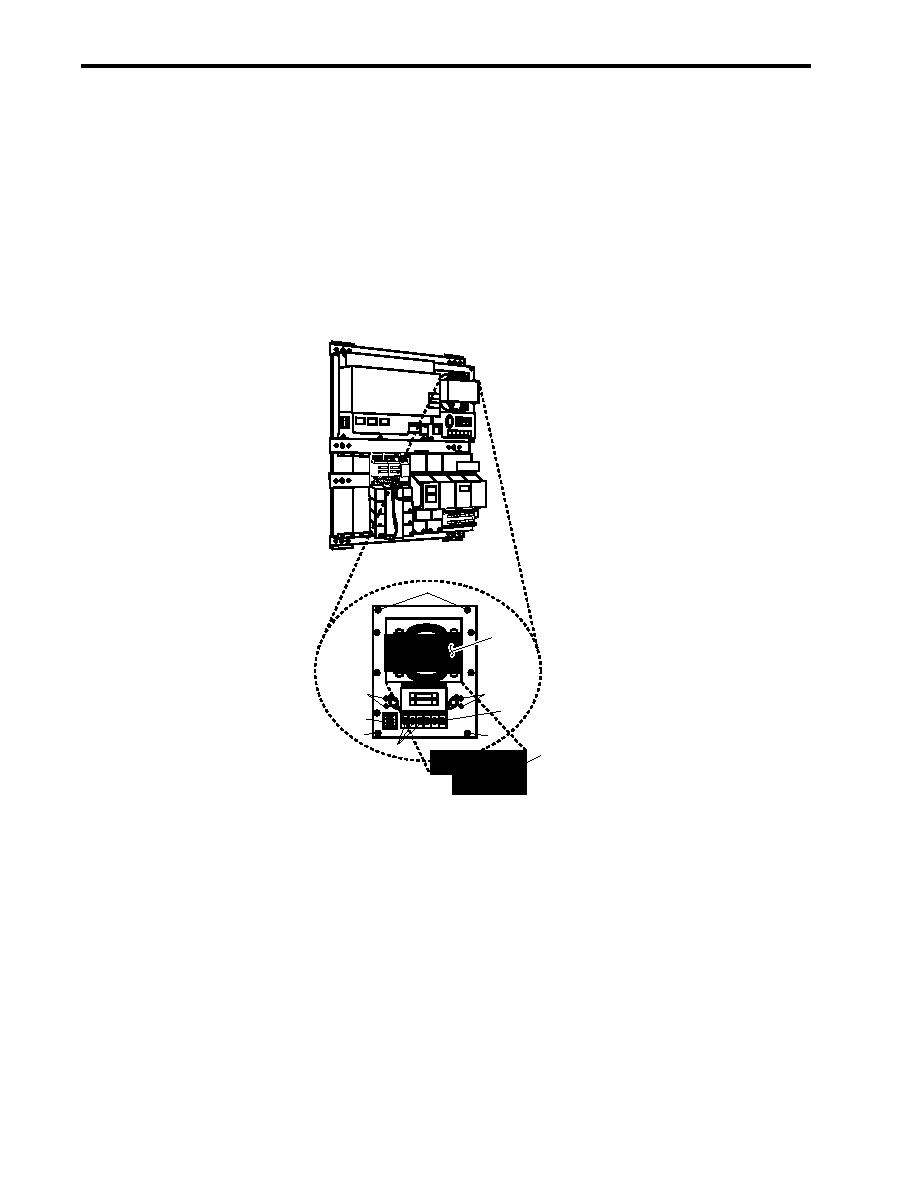
POWER SUPPLY PS-35 REPLACEMENT
REMOVAL
1. OPEN the enclosure following the Open Enclosure procedure of this work package.
2. Label and disconnect the wiring from terminal P1 (figure 1, item 4) and TB1 (figure 1, item 5).
3. Remove the four screws (figure 1, item 6) that secure power supply PS-35 (figure 1, item 7), and remove it
from the enclosure.
CP-35
PS 35
MM-35
BE-35
BC-35
6
7
2
2
5
4
6
6
3
1
MODEL PS-35
FUSES UNDER COVER F2-15A
CAUTION: DIESFCOORNENSERVPCIWGR
ECT O E
B
I N
INPUT 120V 50/60 HZ
RESET
3.5A
OUTPUT 24 VDC, 10A
Figure 1. Power Supply PS-35 Replacement
INSTALLATION
1. Position power supply PS-35 (figure 1, item 7) in the enclosure and secure it in place with the four screws
(figure 1, item 6).
2. Connect the wiring to P1 (figure 1, item 4) and TB1 (figure 1, item 5) using the labels from step 2 of Removal
as a guide. Remove the labels.
3. Perform the Follow-On Service procedure at the end of this work package.
0026 00-2
|
|
Privacy Statement - Press Release - Copyright Information. - Contact Us |
