|
| |
TM 5-4210-233-14&P-1
5-66. APU GENERATOR-Continued
(11)
Check the field winding resistance from F2 in the control box to the F + connection on the
generator (F + is connected to the positive brushes). Resistance should be 1.46 ohms on standard
ac models. Other models will have the following resistances:
2.06 ohms for 24-volt cranking
3.80 ohms for 32-volt cranking
0.80 ohms for transistor flicker
5.14 ohms for 24-volt battery charger
8.8 ohms for 32-volt battery charger
If the windings are warm from running, the resistance will be slightly higher. If the resistance is
high, check for an open circuit in one of the parallel windings, step 12, otherwise go to step 13.
(12) Separate the parallel field windings (at F +) and
check each for open circuit.
(13)
Check for open circuit in the series winding
with ohmmeter. Touch probes to lead S1 and
connection F +. If there is an open circuit,
isolate each coil and check ft.
(14)
Test for short circuit between the starter
windings and the shunt windings. Before
doing this, separate all windings at F +.
(15)
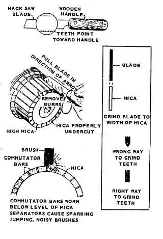
Commutator Repair: The commutator bars
wear down with use, so eventually the mica
between them extends over the tops of the
bars and causes sparking and noisy brushes.
When the mica on any part of the commutator
is touching the brushes, it must be undercut.
A suitable undercutting tool can be made from
a hacksaw blade. Be careful not to injur the
bars. After undercutting, remove any burrs
formed on the bars. Cut the mica to about
1/32" under the bars.
(16)
If the commutator is grooved, out-of-round, or
otherwise damaged, refinish it. Turn it in a
lathe and then undercut the mica as described
above.
Shield
the
ball
bearing
during
refinishing. Do not use turning centers on
shaft because they probably have been
damaged and are no longer true centers.
Commutator and slip ring run out should be
less than .002 in.
(17)
Brush Rig Alignment: The brush rig must
be aligned in the neutral position. If it isn't
sparking will occur. Normally the neutral
position is identified by a yellow mark
extending from the brush rig to the endbell. If
the mark is lost, or a new brush rig installed,
follow these instructions to find the neutral
position.
5-368
|