|
| |
ENGINE DIVISION SERVICE MANUAL
TM 5-4210-230-14&P-1
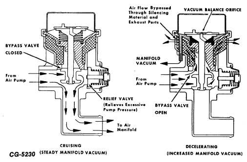
Fig. 69 Typical Diverter Valve Operation
(7)
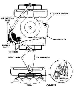
Remove vacuum hose from diverter valve (Fig. 68)
and check for a vacuum pull at the end of hose. If no
vacuum is felt, replace hose.
(8)
Reconnect vacuum hose from diverter valve and
check for momentary flow of air through the diverter
valve exhaust ports (Fig. 69). After a few seconds,
flow of air through the diverter valve exhaust ports
should be restored. If diverter valve does not
function properly, valve is faulty and must be
replaced.
AIR INJECTION SYSTEM FUNCTIONAL
TEST (For California)
The air injection system used on engines sold in
California consists of two separate systems, one system
operating the left bank and the other system operating the
right bank. Each system, consisting of an air pump, diverter
valve and connecting hoses, must be tested individually.
Perform air injection system functional test as follows:
Fig. 70 Air Injection System Used on Small V8
Engine (Except California)
CGES-215 Page 40
|