|
| |
ENGINE DIVISION SERVICE MANUAL
TM 5-4210-230-14&P-1
b.
With engine off, inlet tube damper should be in full
down position to close heat tube inlet pipe from
exhaust manifold stove. Damper position can be
determined by looking in end of inlet tube. If damper
assembly is not in the correct position, vacuum
chamber should be removed and damper movement
loosened. Replace vacuum chamber (located on top
of inlet tube) and recheck damper position.
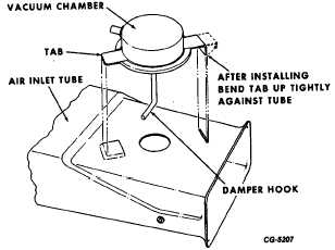
Fig. 42 Vacuum Chamber Details
To replace vacuum chamber (Fig. 42) (cannot be
replaced on air cleaners used on 4-196 engines)
bend tab nearest inlet tube entrance down from
inside tube. Disconnect vacuum hose and lift
vacuum chamber, sliding the rear tab out of its slot
disengaging damper hook from damper. Attach new
chamber by engaging hook in damper, sliding rear
tab into its slot and fitting front tab into place. A
spring preload should be felt when vacuum chamber
is pressed firmly against top of inlet tube. If no
preload is felt, check the installation or be sure parts
are not faulty. Press front vacuum chamber tab
firmly against tube inside surface. Connect vacuum
hose.
c.
Start engine and note that damper has rotated up to
close off cold air inlet. Observe damper position by
looking in the inlet tube. If damper did not
immediately close cold air inlet, proceed as follows:
(1) Shut off engine and disconnect the two hoses from
sensor.
(2) Connect the two hose ends together using suitable
tubing.
(3) Restart engine and again check damper location. If
damper fully closes cold air inlet, temperature sensor is
defective and must be replaced (located inside air cleaner
body).
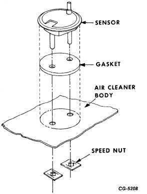
Fig. 43 Sensor Installation
To replace temperature sensor, disconnect two
vacuum hoses attached to sensor inlet and outlet
tubes on underside of air cleaner body. Remove
clamps or speed nuts from tubes and lift sensor from
body. Position new sensor and gasket inside air
cleaner body. Firmly press two new speed nuts or
clamps on tubes to hold sensor in place. Attach
vacuum hoses to sensor tubes. If damper does not
close cold air inlet, sensor is okay, but damper has
bind or vacuum chamber is defective. Remove
vacuum chamber and check damper for free
movement. If damper moves freely, replace vacuum
chamber.
d.
After cold start, operate engine for 10 minutes at
medium RPM. When engine is at normal operating
temperature, slow
CGES-215 Page 25
PRINTED IN UNITED STATES OF AMERICA
|