|
| |
TRUCK SERVICE MANUAL
TM 5-4210-230-14&P-1
REASSEMBLY
REASSEMBLY
Make sure all holes in the new gasket have been properly
punched and that no foreign material has adhered to the
gaskets. Make sure the accelerating pump diaphragm,
secondary operating diaphragm and governor operating
diaphragm are not cut or torn.
An exploded view of the carburetor is shown in Fig. 27.
Throttle Operating Housing
Refer to Figs. 40 and 41 for the correct location of the parts.
1. Install the engine (HOT) idle screw and spring in the
throttle operating housing. Turn the screw in until spring
tension is felt.
2. Install the pump cam retainer screw noting hole position
and reference number on cam and lever. The cast number on
the cam should face toward the throttle operating housing.
Then install the cam.
3. Install the operating lever and shaft assembly. Position
the flats of the throttle shaft driver in relation with the hot idle
adjusting screw.
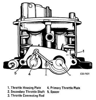
Figure 40 Throttle Operating Housing Plate
4. Bend locking tabs on throttle shaft driver lock washer.
5. Install the accelerating pump lever and the secondary
throttle plate operating lever.
6. Install two throttle operating shaft housing assembly
screws in throttle operating shaft housing.
7. While holding the primary throttle plate in the closed
position, assemble the throttle operating shaft housing on the
throttle body and tighten screws securely.
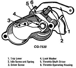
Figure 41 Throttle Operating Housing Assembly
8. If the carburetor is equipped with a safety throttle
redundant spring, install the catch lever assembly on throttle
operating lever shaft.
9. Install the trip lever over the shaft redundant spring perch.
10. Install throttle operating shaft spacer on throttle operating
shaft.
11. Install the curved end of the redundant spring on the short
spring perch.
12. Install the short straight end of the redundant spring on
the long spring perch.
13. Holding the redundant spring concentric with the throttle
operating shaft, install the redundant spring bushing.
14. Install the throttle operating shaft nut lock washer on the
throttle operating shaft.
CGES-125-T Page 28
PRINTED IN UNITED STATES OF AMERICA
|