|
| |
ENGINE DIVISION SERVICE MANUAL
TM 5-4210-230-14&P-1
ENGINE
alternately, evenly and securely. Remove the three
retaining bolts and flatwashers which were installed to
hold the clutch compressed, Figure 49.
NOTE: The clutch will not operate properly unless
these retaining bolts and flatwashers are removed.
23. Position a new water pump mounting gasket on the
cylinder block and install water pump.
NOTE: Use a nonhardening sealing compound on the
water pump capscrews and torque to specified
torque.
Fig. 150 Clutch Installation to Flywheel
1. Cover retaining bolts
2. Retaining bolts for compressing clutch
3. Aligning bar
24. Position new cylinder head gaskets (insure the stamped
"Front" is to the front of the engine) on each bank over the
aligning dowel sleeves insuring that all bolt holes in the
gaskets are in line with those on the cylinder block. Place
cylinder head on the proper bank aligning the head with
the dowel sleeves in the crankcase. Loosely install all
cylinder head bolts and flatwashers.
25. Repeat Step 24 for the opposite cylinder head.
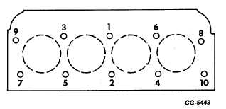
26. Tighten the cylinder head bolts alternately and evenly in
sequence as illustrated in Figure 151 to the torque shown
in the "Torque Chart."
Repeat this operation on the opposite cylinder head. It is
not necessary to retorque the cylinder head bolts after a
run-in period.
27. Install the hydraulic tappets in their respective bores in
the cylinder block.
28. Insert the valve lifter (push) rods in their respective
positions.
29. Place the rocker arms and pivots on their respective
cylinder heads making sure the rocker arms are in line
with the push rods and valves. Install mounting bolts and
tighten to specified torque. See "Torque Chart."
30. Position the intake manifold seals in position in front and
rear of crankcase. See Figure 38.
Fig. 151 Cylinder Head Mounting Bolt Tightening
Sequence
31. Position the tappet cover and intake manifold gasket
assembly on the crankcase. Note the roll pins provided
for proper alignment.
32. Place intake manifold in position making sure the
direction of distributor rotation is located at the front of
the engine. Secure the manifold to the cylinder heads
with bolts and washers. Tighten to specified torque.
NOTE: Use nonhardening sealing compound on bolts
prior to installation. Also, insure that lifting eyes are
installed under the right front and left rear bolts.
33. Place the cylinder head cover gaskets in each cover and
install the cylinder head cover with the oil filler cap on the
right cylinder head securing with screws and washers.
Repeat this operation for opposite cover.
CGES-210 Page 61
PRINTED IN UNITED STATES OF AMERICA
|