|
| |
ENGINE DIVISION SERVICE MANUAL
TM 5-4210-230-14&P-1
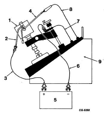
Fig. 9 Distributor-To-Test Stand Wiring
1.
Distributor
4.
Brown Wire
7.
Test Stand Ground Lead
2.
Red Wire
5.
12 Volt Battery
8.
Test Stand Distributor Lead
3.
Jumper Wire
6.
Jumper Wire
9.
Distributor Test Stand
4.
Connect one jumper wire from battery negative (-) post
to test stand ground stud.
5.
Connect other jumper wire from battery positive (+)
post to ring connector on red distributor lead. Test
stand and distributor are now ready to make distributor
operation test. (Refer to Operation Test Procedure.)
Operation Test Procedure
1.
Mount distributor in test stand and connect test leads
as outlined in Preparation of Distributor Test Stand.
2.
Calibrate test stand dwell meter per manufacturers
instructions.
3.
Operate distributor at 300 RPM (with 12-13 volts
primary input) and observe dwell reading. Dwell should
be within specified limits (see Distributor TEST
SPECIFICATIONS). If dwell is not within specified
limits, check trigger wheel-to-sensor air gap.
4.
Check trigger wheel tooth accuracy as follows:
CGES-145-U Page 7
PRINTED IN UNITED STATES OF AMERICA
|