|
| |
ENGINE DIVISION SERVICE MANUAL
TM 5-4210-230-14&P-1
The vacuum advance system incorporates a vacuum
diaphragm unit which rotates the distributor sensor plate in
response to changes in carburetor throttle bore vacuum.
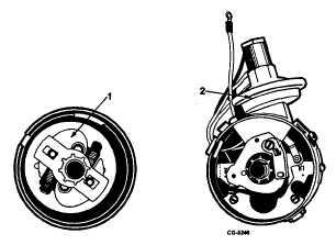
The two systems, mechanical and vacuum (Figure 5)
operate independently, yet work together to provide proper
spark advance.
Fig. 5 Spark Advance Systems
1.
Mechanical (Centrifugal) Advance Mechanism
2.
Vacuum Advance Diaphragm Unit
MAINTENANCE
To perform effectively, the ignition system must be
properly maintained. It is important that ignition system
maintenance operations be performed at the specified time or
mileage intervals.
For ignition system maintenance intervals, procedures
and specifications, refer to the appropriate "Emission Control
Systems and Service Operations" section of the Truck Service
Manual as listed below.
For vehicles built in 1978, see
CTS-2733
For vehicles built in 1979, see
CGES-135
For vehicles built in 1980, see
CGES-215
For vehicles built in 1981, see
CGES-300
DISTRIBUTOR SERVICE
DISTRIBUTOR REMOVAL
1.
Unfasten distributor cap retaining clips. Remove
distributor cap (with high tension cables) and position it
out of the way.
2.
Disconnect vacuum hose from distributor vacuum
advance unit, if equipped.
3.
Disconnect distributor wiring as follows:
a.
Disconnect distributor leads from positive and
negative terminals of. ignition coil.
b.
Disconnect deceleration throttle modulator lead
(white wire) at connector (where used).
4.
Disconnect tachometer drive cable, if equipped.
5.
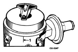
Scribe a mark on distributor housing in line with tip of
rotor (Figure 6) and note position of rotor and
distributor housing in relation to surrounding engine
parts as reference points for reinstalling distributor.
Fig. 6 Rotor Position Reference Mark
1.
Scribe Mark
6.
Remove distributor hold-down bolt and clamp.
7.
Carefully withdraw distributor from engine. Do not lose
gasket or "O" See Figure 7 for gasket or "O" ring
location on distributor.
CGES-145-U Page 5
PRINTED IN UNITED STATES OF AMERICA
|