|
| |
TM5-4210-229-14&P
6-15.
TRANSMISSION REPAIR (Continued).
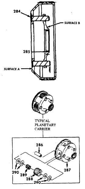
(h) Using a lathe with a four jaw chuck, mount
the carrier with surface A facing the chuck.
Insert the six fabricated dummy pins (284)
into the pinion pin holes. Adjust the chuck,
centering the carrier based on surface B
and the runout of the dummy pins (284).
(i) Total runout of the bushing (285) after
boring must not exceed 0.002 inch (0.05
mm).
NOTE
The
hydraulic
press,
used
with
planetary rebuilding set, should have a
ten ton (9000 kg)capacity, an adjustable
press bed of 25 inches (64 cm)
minimum opening and a pressure
gauge to assist in determining proper
installation and staking of the pinion
pins.
(j) Using a drill that is slightly smaller than the
pinion pin (286) diameter, drill into the
swaged ends of the pins (only one end
required). Do not drill into the carrier. The
rear ends of all pinion pins except those in
the center carrier assembly will be drilled.
Drill the front ends of the center assembly
pins.
(k) Place press fixture in a hydraulic press.
Select the proper spacer and adapter, if
required, from the special tool chart.
Position these parts (if used) to support the
carrier assembly (drilled ends of pinion
pins upward) solidly on the press fixture.
(I) Install pin remover into the ram of the
press fixture. Press the pinion pins (286)
from the carrier assembly (287).
(m) Remove the pinion groups, consisting of
pinions (288), bearings (289) and thrust
washers (290).
(n) Lubricate needle rollers (289) and thrust
washers (290) with oil-soluble grease
(Appendix D, Item 21) before assembling
the pinion groups. Assemble all of the
pinion groups for the carrier assembly
(287).
Each
group
is
assembled
by
inserting-the proper loading pin into the
bore of the pinion, installing the needle
roller bearings around the loading pin,
installing a steel thrust washer at each end
of the pinion, and installing a bronze thrust
washer onto each steel thrust washer.
(o) Position the carrier assembly (287) rear
end upward (except the center carrier).
Install all pinion groups into the planetary
carrier, aligning the loading pins with the
pin bores in the carrier.
6-76
|