|
| |
TM5-4210-229-14&P
6-9. CAMSHAFT AND GEAR MAINTENANCE (Continued).
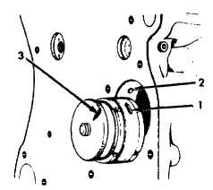
a. If the camshaft bushings were removed, install
new bushings using the camshaft bushing puller
and installer tool from the camshaft bearing ser-
vice set. Be sure the oil holes in the bushing (1)
line up with the oil holes in the crankcase (2).
b. To ease oil hole alignment, mark the back-up
nut (3) in line with the bushing oil hole (1) when
installing the bushings.
c. Camshaft gear replacement.
(1) The drive gear on the camshaft must be
pressed off since it is a shrink fit.
(2) Place the thrust plate on the keyway end of
the camshaft against the bearing journal.
(3) Insert the woodruff key into the keyway.
NOTE
Use a Thermomelt crayon to determine
temperature.
(4) Heat the camshaft gear to approximately 400° F
(205° C).
Wear asbestos gloves when installing gear.
(5) Press the gear against the shoulder on the
shaft with the timing mark pointed out-
ward.
d. Coat the cam lobes, bearings and journals with
clean engine oil (Appendix D, Item 37) and
install the camshaft.
e. Install the camshaft so that the timing marks
stamped on each gear are in line.
f. Alternately torque the thrust plate cap screws
to 20 ft-lb (27 N.m) torque.
g. Check the camshaft end play with a dial indicator.
End play should be 0.005 to 0.013 in (0.13 to
0.33 mm).
h. Install front cover (paragraph 6-8).
i. Install cylinder head and valves (paragraph 6-6).
6-10. TIMING AND GEAR TRAIN MAINTENANCE
This task cover: a. Removal
b. Inspection
c. Installation
INITIAL SET-UP
Tools
Dial Indicator
General Mechanics Tool Kit
Equipment Condition
Para. Condition Description
6-9 Camshaft and Gear Removed
Materials/Parts
Idler Gear (675764C1)
Injection Pump Drive Gear (1802737C1)
Cleaning Solvent (Appendix D, Item 54)
Grease (Appendix D, Item 21)
6-20
|