|
| |
TM 5-4210-229-14&P
6-6.
CYLINDER HEAD AND VALVES MAINTENANCE (Continued)
(b) Lightly polish valve surface with extremely
fine emery cloth (Appendix D, Item 13).
(2) Visually inspect each valve for excessive wear,
burn marks, warpage, pitting, or scuffing at valve
stem grooves, valve stems, or valve heads.
Replace valves which are seriously bent, worn,
burnt, warped, pitted, or scuffed.
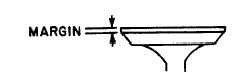
INSTALLATION
a. Resurface
valve
face
angle,
if
necessary.
Maintain a minimum valve face margin of 0.068
in.(1.73 mm) for intake valves and 0.045 in.(1.14
mm) for exhaust valves.
b.
Set valve in grinder to desired angle.
c.
Dress the wheel to proper angle.
d.
Take a light cut off valve face angle surface.
e.
Replace valve if more than 0.008 in. (0.20 mm)
stock is removed from valve face angle or if
margin falls below minimum specifications.
f.
Check valve face run out, after resurfacing, with
dial indicator.
g.
Replace valve if run out (in reference to valve stem)
is greater than 0.002 in. (0.05 mm) total variation in
dial indicator reading.
h.
After resurfacing valves, clean valve guides and
check valve face contact with valve seat using
bluing ink (Appendix D, Item 23).
(1) Spread thin film of bluing ink (Appendix D,
Item 23) on valve face. Insert valve into
its guide.
(2) Apply pressure on exact center of valve head,
while making a quarter turn in the seat.
(3) Remove valve, inspect impression made on
seat and on valve face.
(4) Bluing ink (Appendix D, Item 23) should
appear around entire contact surface of valve
face and valve seat to be acceptable. Check several
times to prevent error. If acceptable, proceed with
valve installation.
NOTE
If bluing ink (Appendix D, Item 23) DOES NOT
show around the entire contact surface of the
valve seat, the angles do not match and are
unacceptable. If this happens, correct
resurfacing valve seats; not valve faces.
i.
Valve seat resurface.
(1) Dress the grinding wheel to correct angle.
lightly lubricate and install correct size pilot
into valve guide bore.
(2) Lower grinder head over pilot shank until
wheel barely clears the valve seat. Turn on
power. Gently apply grinding wheel to valve
seat with little pressure other than weight of
the wheel.
(3) Raise
wheel
frequently
to
prevent
overheating.
(4) Grind seat to a smooth even surface.
(5) Check seat concentricity, roundness and
valve
face
contact
using
bluing
ink
(Appendix D, Item 23) following installation
procedure h.(6) After grinding seats, it may
be found that seats are wider than the
specified width.(7) Correct wide valve seats
by grinding top edge of seat with a stone
mounted on grinder head. The stone must
be smaller angle (preferably 15 degrees)
than the valve seat.
NOTE
If
valve
does
not
seat
properly
after
resurfacing valve seats, replace valve seats.
6-10
|