|
| |
TM 5-4210-229-14&P
6-6.
CYLINDER HEAD AND VALVES MAINTENANCE (Continued).
j.
Valve seat replacement.
(1) Remove valve seats with a slide hammer and
expanding screw with pre-cup puller. Two
pre-cup pullers are available for service; one for
intake, one for exhaust valves.
Cleaning solvent (Appendix D, Item 54) is both
toxic and flammable. Keep off skin. Use only
in a well-ventilated area and avoid prolonged
breathing of vapors. Keep away from open
flames.
(2) Clean counter bore (in head) to assure pro-per
valve seat mating and good heat transfer. Use
cleaning solvent (Appendix D, Item54) and brass
wire brush (Appendix D, Item7).
(3) If right fit is not assured between mating surfaces
of valve seat and cylinder head counterbore,
install oversize valve seat inserts as follows:
(a) Take a light cut from bottom in insert
counterbore in cylinder head to dimensions
shown below:
OVERSIZE INTAKE
EXHAUST
INSERT
.002 in
1.998-1.999 in.
1.626-1.627 in.
(50.75-50.77 mm)
(41.30-41.33 mm)
.015 in.
2.011-2.012 in.
1.639-1.640 in.
(51.08-51.10 mm)
(41.63-41.66 mm)
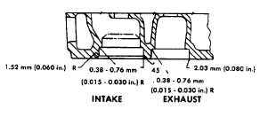
(b) Maintain
radii
shown
when
enlarging
counterbore for oversize inserts.
NOTE
Chilling will prevent metal scraping at
counterbore, ensuring maximum contact
of
mating
surfaces.
(4)
Valve seat inserts installation.
(a)
Chill valve set inserts and driver tool in dry
ice or liquid freon for one half hour before
installing.
(b)
Align insert to avoid cocking.
(c)
Press insert into cylinder head using an
arbor press and insert driver. Exert an
even pressure of 500 ft-lb (2225 N.m) for
five seconds to assure proper seating.
(d)
Insert should be recessed into head when
properly seated.
k.
Coat valve stems with clean engine oil (Appendix D,
Item 36) prior to inserting them from the bottom of the
head.
6- 11
|