|
| |
TM5-4210-229-14&P
Section XXIV. MAINTENANCE OF STEERING ASSEMBLY
Para.
Drag Link Replacement........................................... 4-178
General ................................................................... 4-175
Para.
Pitman Arm Replacement....................................... 4-176
The Rod Replacement............................................ 4-177
4-175. GENERAL.
This section contains information the maintenance of the steering assembly components that are maintainable at
the Organizational level.
4-176. PITMAN ARM REPLACEMENT.
This task covers:
a. Removal
b. Installation
Initial SET-UP
Tools
General Mechanics Tool Kit
Materials/Parts
Pitman Arm (488704C1)
General Safety Instructions
Engine OFF.
Transmission in (N) neutral.
Parking brake set.
Battery selector switch OFF.
REMOVAL
a.
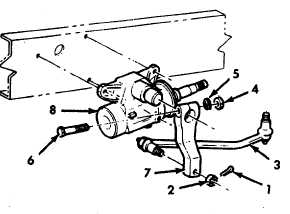
Remove cotter pin (1) from the attaching nut (2).
b.
Remove nut (2).
c.
Remove the drag link (3) from the pitman arm.
d.
Remove the nut (4) and lockwasher (5) from the
pinch bolt (6) that secures the pitman arm
(7) to
the steering gear (8) sector
shaft.
e.
Drive wedge into slot in pitman arm (7). Remove
pitman arm (7).
INSTALLATION
a.
Position the pitman arm (7) on the sector shaft,
aligning the timing mark on the sector shaft to the
timing mark on the pitman arm. Use the pinch bolt (6)
to align the groove on the sector shaft and the bolt hole
in the pitman arm (7).
b.
Remove the wedge, making certain that the pitman
arm (7) stays aligned to the sector shaft.
c.
Install lockwasher (5) and nut (4) and torque nut (4)
to 330-370 ft-lb (447-502 N.m).
d.
Install ball stud of drag link (3) into the pitman arm
(7).
e.
Install nut (2) and torque to 110-125 ft-lb (149-169
N.m).
f.
Install cotter pin (1).
NOTE
If cotter pin cannot be installed after obtaining
minimum torque, do not back off nut. Tighten to next
castellation.
4-192
|