 |
|||
|
|
|||
|
|
|||
| ||||||||||
|
|
 TM 5-4210-224-14&P
5-9. ALTERNATOR REPAIR (Continued).
(2) Reverse the test leads so that the positive test lead is connected to the negative heat sink. The negative
test lead should now be touched to each diode terminal. If the test lamp fails to light, an open diode is
indicated.
(3) If a shorted or open diode is detected replace the entire heat sink assembly.
ASSEMBLY
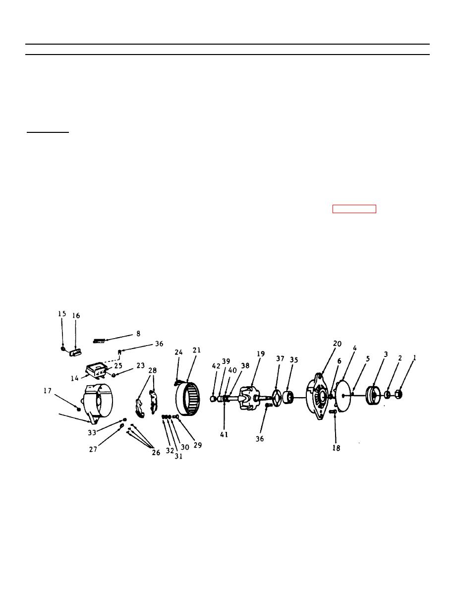
a. Install bearing (42) on the inner race of the bearing (19).
b. Press on new slip ring assembly (39 thru 41) making sure the slot lines up with the slot in the shaft. The new slip
ring assembly should be pressed on the shaft with enough pressure to prevent the insulation washer (41) from
turning.
c. Solder the rotorcoil leads (38) to slip ring assembly using a heat gun and solder (Appendix D, Item 43a).
d. Place slip ring end of rotor shaft (19) into an arbor press. Install the rotor and drive end housing (20) by pressing
the housing and bearing (35) on rotor shaft.
e. Install the stator (21) on the slip ring end housing (22) and align bolt holes in stator (21) with housing (22).
f. Install three stator terminals (24) on the terminal board studs (25) and secure with lock nuts (23).
5-18
|
|
Privacy Statement - Press Release - Copyright Information. - Contact Us |
