|
| |
TM 5-4210-220-34
2-21.
FRONT AXLE - Continued
2-21.2
Differential Carrier - Continued
(3)
Apply press load (see chart below) to the assembly and check rolling torque. Wrap soft wire around the
bearing cage, attach spring scale and pull. Preload is correct when torque required to rotate the pinion
bearing cage is from 10 20 in. lb (1.1 2.3 Nm). This specification is translated into spring scale readings in
the chart below.
(4)
If necessary, adjust pinion bearing preload by changing the pinion bearing spacer. A thicker spacer will
decrease preload. A thinner spacer will increase preload.
NOTE
Once correct bearing preload has been established, note the spacer size used. Select a spacer 0.001 in.
(0.03 mm) larger for use in the final pinion bearing cage assembly. The larger spacer compensates for
slight "growth" in the bearings which occurs when they are pressed on the pinion shank. The trial build-up
will result in proper pinion bearing preload in three of four cases. Do not assume that all assemblies will
retain proper preload once bearings are pressed on pinion shank. FINAL PRELOAD TEST MUST BE
MADE IN EVERY CASE.
Specifications for Pinion Bearing
Spring Scale Reading
Trial Build-up Preload Test
(without pinion seal)
Nominal Bearing
Spacer Thickness
Press Loads
in.
mm
Tons
Metric Tons
lbs.
kgs.
Front Axle
0.638
16.2
13.5-15.5
12.2-14.0
4-8
2-4
Rear Axle
0.496
12.6
17-19
15.4-17.2
3-7
2-3
d.
Pinion Bearing Preload - Final Test And Adjustment
NOTE
Rear axle pinion is equipped with helical
gear. For easier disassembly during
bearing adjustment procedure, use a
dummy yoke in place of helical gear.
(1)
Apply clamp load to the pinion bearing cage
assembly. Either install the yoke (or helical
gear) and torque the pinion nut to specifications
or use a press to simulate nut torque (see chart
below).
Vise Method - If the yoke and nut are used,
mount the assembly in a vise, clamping yoke
firmly.
Press Method - If a press is used, position a
sleeve or spacer so that load is applied directly
to the backface of the outer bearing cone.
(2)
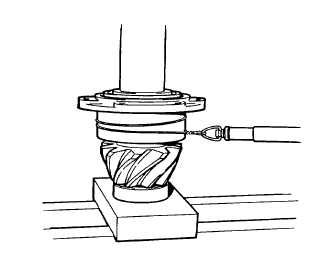
Measure pinion bearing preload by using a spring scale to test the assembly rolling torque.
To use the spring scale, wrap soft wire around the bearing cage, attach the scale and pull. Preload is correct
when torque required to rotate the pinion bearing cage is from 15 35 in. lb (1.7 4.0 Nm). This specification is
translated into spring scale readings in the chart below.
2-300
|