|
| |
TM 5-4210-220-34
2-21.
FRONT AXLE - Continued
(3)
If necessary, adjust the contact pattern by
moving the ring gear and drive pinion. Ring
gear position controls the backlash. This
adjustment moves the contact pattern along
the face width of the gear tooth. Pinion
position is determined by the size of the
pinion bearing cage shim pack. It controls
contact on the tooth depth of the gear tooth.
These adjustments are interrelated. As a
result, they must be considered together
even though the pattern is altered by two
distinct operations. When making
adjustments, first adjust the pinion, then
the backlash. Continue this sequence until
the pattern is satisfactory.
(4)
If the gear pattern shows incorrect tooth
depth contact, change drive pinion position
by altering the shim pack. Used gears
should achieve proper contact with the
same shims removed from the axle during
disassembly.
(5)
If the pattern Is too close to the top land of
the gear tooth, remove pinion shims.
(6)
If the pattern is too close to the root of the
gear tooth, add pinion shims.
NOTE
Check ring gear backlash after each shim change and readjust as necessary to maintain 0.006 0.016 in.
(0.16 0.41 mm).
(7)
If the gear pattern shows incorrect face width contact, change backlash.
(8)
With the pattern concentrated at the toe (too far down the tooth), add backlash, see a. preceding.
(9)
If the pattern is concentrated at the heel (to far up the tooth), remove backlash see a. preceding.
c.
Pinion Bearing Preload Adjustment Preliminary
(1)
Assemble pinion bearing cage, bearings
and spacer (without drive pinion or oil seal).
Center bearing spacer between two bearing
cones.
NOTE
When new gear set or pinion bearings
are used, select nominal size spacer
from the specification chart below. If
original parts are used, use spacer
removed during disassembly.
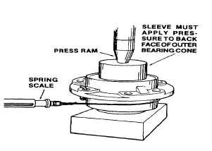
(2)
With the bearings well lubricated, place the
assembly in a press. Position sleeve so
that load is applied directly to the backface
of the outer bearing cone.
2-299
|